Toyota
Nissan Versa
 Sedan Service Manual
Transmission & driveline » Transaxle & transmission (TM)
5Th main gear assembly

Removal and Installation

REMOVAL

  1. Move the shift selector to the 3rd gear position.
  2. Disconnect the shifter cable and the selector cable from shifter lever A and selector lever. Refer to TM, "Removal and Installation".

    CAUTION: Do not move shifter lever A and selector lever to disconnect each cable.

  3. Drain gear oil. Refer to TM, "Draining".
  4. Remove fender protector (LH). Refer to EXT, "Removal and Installation".
  5. Remove the harness clamp (A) from rear housing (1).

REMOVAL

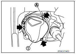
  1. Remove rear housing and O-ring.

    CAUTION: Remove in direction of input shaft ( ) as shown. Rear 
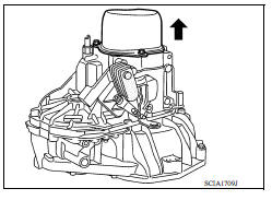
housing oil channel is inserted to input shaft center hole.

  2. Remove 5th main gear assembly. Refer to step 5 through 8 of "Disassembly of TRANSAXLE ASSEMBLY". Refer to TM, "Disassembly".

REMOVAL

INSTALLATION

Installation is in the reverse order of removal.

  • Shift into 3rd with shifter lever to install the 5th main gear assembly, referring to Step 36 to 39 of "Assembly of TRANSAXLE ASSEMBLY" Refer to TM, "Assembly".
  • Install O-ring and the rear housing to the transaxle case and tighten the bolts to the specified torque. Refer to TM, "Exploded View".

            CAUTION:

  • Do not reuse O-ring.
  • Do not pinch O-ring when installing rear housing.
  • Refill gear oil. Refer to TM, "Refilling".

Inspection

INSPECTION AFTER INSTALLATION

  • Check the operation of the control linkage. Refer to TM, "Inspection".
  • Check the oil level and for oil leakage. Refer to TM, "Inspection".
    More about «Transaxle & transmission (TM)»:

    Precautions

    Structure and operation

    Position switch

    Gear oil

    Side oil seal

    Position switch

    Control linkage

    Air breather hose

    5Th main gear assembly

    Transaxle assembly

    Transaxle assembly

    Input shaft and gear

    Mainshaft and gear

    Final drive

    Precautions

    A/T Control system

    A/T Shift lock system

    Transaxle

    A/T control system

    Line pressure control

    Shift change control

    Lock-up control

    Diagnosis description

    Consult function

    TCM

    Diagnosis and repair work flow

    Additional service when replacing TCM

    Additional service when replacing transaxle assembly

    A/T Fluid cooler

    Stall test

    Line pressure test

    U0073 Communication bus a off

    U0100 Lost communication (ECM A)

    U0140 Lost communication (BCM)

    U0155 Lost communication (IPC)

    U0300 Can communication data

    U1000 Can comm circuit

    U1117 Lost communication (ABS)

    P062F EEPROM

    P0705 Transmission range switch A

    P0706 Transmission range sensor A

    P0711 Transmission fluid temperature sensor A

    P0712 Transmission fluid temperature sensor A

    P0713 Transmission fluid temperature sensor A

    P0717 Input speed sensor A

    P0720 Output speed sensor

    P072C Stuck in 1GR

    P072D Stuck in 2GR

    P072E Stuck in 3GR

    P072F Stuck in 4GR

    P0731 1GR Incorrect ratio

    P0732 2GR Incorrect ratio

    P0733 3GR Incorrect ratio

    P0734 4GR Incorrect ratio

    P073E Unable to engage r range

    P073F Unable to engage 1GR

    P0740 Torque converter

    P0743 Torque converter

    P0744 Torque converter

    P074A Unable to engage 2GR

    P074B Unable to engage 3GR

    P074C Unable to engage 4GR

    P0863 TCM Communication

    P0890 TCM

    P0962 Pressure control solenoid A

    P0963 Pressure control solenoid A

    P0973 Shift solenoid A

    P0974 Shift solenoid A

    P0976 Shift solenoid B

    P0977 Shift solenoid B

    P0979 Shift solenoid C

    P0980 Shift solenoid C

    P0982 Shift solenoid D

    P0983 Shift solenoid D

    P2760 Torque converter

    Main power supply and ground circuit

    Overdrive control switch

    O/D OFF indicator lamp

    Shift position indicator circuit

    Shift lock system

    A/T Fluid

    A/T Shift selector

    Control cable

    Key interlock cable

    TCM

    Oil pan

    Output speed sensor

    Differential side oil seal

    Fluid cooler tube

    Transmission assembly

    Service data and specifications (SDS)

    Precautions

    Component parts

    Shift lock system

    Structure and operation

    Fluid cooler & fluid warmer system

    CVT Control system

    Line pressure control

    Shift control

    Lock-up control

    Idle neutral control

    Diagnosis system (TCM)

    TCM

    Diagnosis and repair work flow

    Additional service when replacing TCM

    Additional service when replacing transaxle assembly

    Calibration of G Sensor

    CVT Fluid cooler system

    Stall test

    Line pressure test

    U0073 Communication bus A off

    U0100 Lost communication (ECM A)

    U0140 Lost communication (BCM)

    U0141 Lost communication (BCM A)

    U0155 Lost communication (IPC)

    U0300 Can communication data

    U1000 Can COMM circuit

    U1117 Lost communication (ABS)

    P062F EEPROM

    P0705 Transmission range sensor A

    P0706 Transmission range sensor A

    P0711 Transmission fluid temperature sensor A

    P0712 Transmission fluid temperature sensor A

    P0713 Transmission fluid temperature sensor A

    P0715  Input speed sensor A

    P0720 Output speed sensor

    P0740 Torque converter

    P0743 Torque converter

    P0744 Torque converter

    P0746 Pressure control solenoid A

    P0846 Transmission fluid pressure SEN/SW B

    P0847 Transmission fluid pressure SEN/SW B

    P0848 Transmission fluid pressure SEN/SW B

    P0863 TCM Communication

    P0890 TCM

    P0962 Pressure control solenoid A

    P0963 Pressure control solenoid A

    P0965 Pressure control solenoid B

    P0966 Pressure control solenoid B

    P0967 Pressure control solenoid B

    P0998 Shift solenoid F

    P0999 Shift solenoid F

    P099B Shift solenoid G

    P099C Shift solenoid G

    P1586 G Sensor

    P1588 G Sensor

    P2765 Clutch B speed sensor

    P2857 Clutch A pressure

    P2858 Clutch B pressure

    P2859 Clutch A pressure

    P285A Clutch B pressure

    Main power supply and ground circuit

    Overdrive control switch

    OD OFF indicator lamp

    Shift position indicator circuit

    Shift lock system

    CVT Control system

    CVT Fluid

    CVT Shift selector

    Control cable

    Key interlock cable

    TCM

    Air breather hose

    G Sensor

    Oil pan

    Primary speed sensor

    Secondary speed sensor

    Output speed sensor

    Differential side oil seal

    Water hose

    Fluid cooler hose

    PLUG

    Transmission assembly

    Service data and specifications (SDS)

    Nissan Versa Sedan Service Manual / Transmission & driveline / Transaxle & transmission (TM) / 5Th main gear assembly

    Nissan Versa Sedan Service Manual

    Categories


    © 2017-2024 Copyright www.niveguide.com