Nissan Versa (N17): A/T Control system
A/T Control system : component parts location
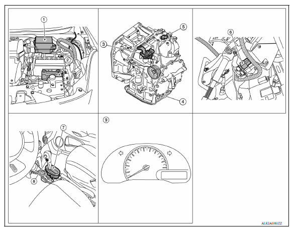
1. IPDM E/R 2. TCM 3. Transmission range switch 4. A/T unit 5. Output speed sensor 6. Stop lamp switch 7. A/T shift selector 8. Overdrive control switch 9. Combination meter (type B)
A/T Control system : component description
| Name |
Function |
| TCM | TM, "A/T CONTROL SYSTEM : TCM" |
| Transmission range switch | TM, "A/T CONTROL SYSTEM : Transmission Range Switch" |
| Input speed sensor | TM, "A/T CONTROL SYSTEM : Input Speed Sensor" |
| Output speed sensor | TM, "A/T CONTROL SYSTEM : Output Speed Sensor" |
| A/T fluid temperature sensor | TM, "A/T CONTROL SYSTEM : A/T Fluid Temperature Sensor" |
| Low clutch solenoid valve | TM, "A/T CONTROL SYSTEM : Low Clutch Solenoid Valve" |
| 2-4 brake solenoid valve | TM, "A/T CONTROL SYSTEM : 2-4 Brake Solenoid Valve" |
| Select ON-OFF solenoid valve | TM, "A/T CONTROL SYSTEM : Select Switch On-Off Solenoid Valve" |
| High clutch/low & reverse brake solenoid valve | TM, "A/T CONTROL SYSTEM : High Clutch/Low & Reverse Brake Solenoid Valve" |
| Torque converter clutch solenoid valve | TM, "A/T CONTROL SYSTEM : Torque Converter Clutch Solenoid Valve" |
| Line pressure solenoid valve | TM, "A/T CONTROL SYSTEM : Line Pressure Solenoid Valve" |
| Accelerator pedal position sensor | TM, "A/T CONTROL SYSTEM : Accelerator Pedal Position Sensor" |
| Overdrive control switch | TM, "A/T CONTROL SYSTEM : Overdrive Control Switch" |
| O/D OFF indicator lamp | TM, "A/T CONTROL SYSTEM : O/D OFF Indicator Lamp" |
| Stop lamp switch | Stop lamp switch detects the operation status of brake pedal. |
| ECM |
|
| BCM | The TCM receives the following signal via CAN
communications from the BCM for judging
the vehicle driving conditions.
|
| ABS actuator and electric unit (control unit) | The TCM receives the following signal via CAN
communications from the ABS actuator
and electric unit (control unit) for judging the vehicle driving
conditions.
|
| Combination meter | The TCM receives the following signal via CAN
communications from the combination
meter for judging the driving request from the driver.
|
A/T Control system : TCM
- The vehicle driving status is judged based on the signals from the sensors, switches, and other control units, and the optimal transaxle control is performed.
- The primary control consists of the following 8 control types.
- Line pressure control
- Gear shift control
- Shift control
- Lock-up control
- Control between each control unit and the A/T (CAN communications control)
- Self-diagnosis function
- Fail-safe function
- Communications control with CONSULT
A/T Control system : transmission range switch
- The transmission range switch is installed to upper part of transaxle case.
- The transmission range switch detects the selector lever position.
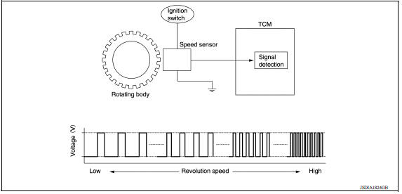
A/T Control system : input speed sensor
- The input speed sensor is installed to control valve.
- The input speed sensor detects input shaft speed.
- The input speed sensor generates ON-OFF pulses (short waveform signal) in proportion to the rotating speed, such that the changing cycle is shorter when the rotating speed increases. The TCM judges the rotating speed from the changing cycle of this pulse signal.
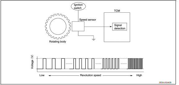
A/T Control system : output speed sensor
- The output speed sensor is installed to the back side of transaxle case.
- The output speed sensor detects output gear speed. The TCM judges the vehicle speed from the rotating speed of the output gear.
- The output speed sensor generates ON-OFF pulses (short waveform signal) in proportion to the rotating speed, such that the changing cycle is shorter when the rotating speed increases. The TCM judges the rotating speed from the changing cycle of this pulse signal.
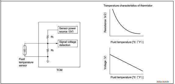
A/T Control system : a/t fluid temperature sensor
- A/T fluid temperature sensor is installed to control valve.
- A/T fluid temperature sensor detects A/T fluid temperature in oil pan.
- The fluid temperature sensor uses a thermistor, and changes the signal voltage by converting changes in the A/T fluid temperature to a resistance value. The TCM judges the A/T fluid temperature based on that signal voltage.
A/T Control system : low clutch solenoid valve
- The low clutch solenoid valve is installed to control valve.
- The low clutch solenoid valve adjusts the pressure to the low clutch
engage pressure and disengage pressure.
For information about the low clutch, refer to TM, "A/T CONTROL SYSTEM : Component Description".
- The low clutch solenoid valve utilizes a linear solenoid valve [N/H (normal high) type].
NOTE:
- The principle of the linear solenoid valve utilizes the fact that the force pressing on the valve spool installed inside the coil increases nearly in proportion to the current. This allows it to produce a fluid pressure that is proportional to this pressing force.
- The N/H (normal high) produces oil pressure when the coil is not energized.
A/T Control system : 2-4 brake solenoid valve
- 2-4 brake solenoid valve is installed to control valve.
- The 2-4 brake solenoid valve adjusts the pressure of the 2-4 brake band
engage and disengage pressures.
For information about the 2-4 brake band, refer to TM, "A/T CONTROL SYSTEM : Component Description".
- The 2-4 brake solenoid valve utilizes a linear solenoid valve [N/L (normal low) type].
NOTE:
- The principle of the linear solenoid valve utilizes the fact that the force pressing on the valve spool installed inside the coil increases nearly in proportion to the current. This allows it to produce a fluid pressure that is proportional to this pressing force.
- The N/L (normal low) produces oil pressure when the coil is not energized.
A/T Control system : select switch on-off solenoid valve
- The select switch ON-OFF solenoid valve is installed to control valve.
- The selector switch ON-OFF solenoid valve controls the switch valve that switches the oil pressure applied to the low & reverse brake and the reverse clutch.
- The selector switch ON-OFF solenoid valve utilizes an ON-OFF solenoid valve.
NOTE:
- The only operations of the valve spool installed inside the coil are pressing or not pressing the ball which seals the hydraulic supply section into the seat. This A/T uses N/L (normal low) type.
- When voltage is not applied to the coil, the force of the pilot pressure presses the ball against the seat, stopping the pilot pressure at that point.
- When voltage is applied to the coil, the valve is pulled in the direction of the coil, disengaging the hydraulic seal which the ball creates. This supplies pilot pressure to the operating locations.
A/T Control system : high clutch/low & reverse brake solenoid valve
- The high clutch/low & reverse brake solenoid valve is installed to control valve.
- The high clutch/low & reverse brake solenoid valve adjusts the pressure to the high clutch and low & reverse brake engage pressure and disengage pressure.
- The high clutch/low & reverse brake solenoid valve utilizes a linear solenoid valve [N/H (normal high) type].
NOTE:
- The principle of the linear solenoid valve utilizes the fact that the force pressing on the valve spool installed inside the coil increases nearly in proportion to the current. This allows it to produce a fluid pressure that is proportional to this pressing force.
- The N/H (normal high) produces oil pressure when the coil is not energized.
A/T Control system : torque converter clutch solenoid valve
- The torque converter solenoid valve is installed to control valve.
- The torque converter solenoid valve controls the lock-up control valve. For information about the lock-up control valve, refer to TM, "A/T CONTROL SYSTEM : Component Description".
- The high clutch solenoid valve utilizes a linear solenoid valve [N/H (normal low) type].
NOTE:
- The principle of the linear solenoid valve utilizes the fact that the force pressing on the valve spool installed inside the coil increases nearly in proportion to the current. This allows it to produce a fluid pressure that is proportional to this pressing force.
- The N/L (normal low) type does not produce oil pressure when the coil is not energized.
A/T Control system : line pressure solenoid valve
- The line pressure solenoid valve is installed to control valve.
- The line pressure solenoid valve controls the line pressure control valve. For information about the line pressure control valve, refer to TM, "A/T CONTROL SYSTEM : Component Description".
- The line pressure solenoid valve utilizes a linear solenoid valve [N/H (normal high) type].
NOTE:
- The principle of the linear solenoid valve utilizes the fact that the force pressing on the valve spool installed inside the coil increases nearly in proportion to the current. This allows it to produce a fluid pressure that is proportional to this pressing force.
- The N/H (normal high) produces oil pressure when the coil is not energized.
A/T Control system : accelerator pedal position sensor
- The accelerator pedal position sensor is installed above the accelerator pedal.
- The accelerator pedal position sensor detects the amount that the accelerator pedal is depressed.
- The accelerator pedal position sensor converts the amount of accelerator pedal depression into a voltage signal. The ECM judges the throttle position based on this voltage signal, and sends it via CAN communication to the TCM.
A/T Control system : overdrive control switch
- The overdrive control switch is installed on the selector lever knob.
- If the overdrive control switch is pressed when the O/D OFF indicator lamp on the combination meter is not lit, the status changes to overdrive OFF and the O/D OFF indicator lamp illuminates.
- If the overdrive control switch is pressed when the O/D OFF indicator lamp on the combination meter is lit, the overdrive OFF status is canceled and the O/D OFF indicator lamp turns off.
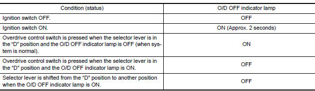
A/T Control system : o/d off indicator lamp
- The O/D OFF indicator lamp is positioned on the combination meter.
- The O/D OFF indicator lamp illuminates when the overdrive function is deactivated (O/D OFF).
- For checking the bulb, this lamp turns on for a certain period of time when the ignition switch turns ON, and then turns off.
 Precautions
A/T Shift lock system
A/T Shift lock system : component parts location 1 Stop lamp switch. 2 Shift lock release lever. 3 Park position switch. 4 Shift lock solenoid. A/T Shift lock system : component description ...
Other materials:
Evaporative emission system
EVAPORATIVE EMISSION SYSTEM : System Diagram
EVAPORATIVE EMISSION SYSTEM : System
Description
INPUT/OUTPUT SIGNAL CHART
Sensor
Input signal to ECM
ECM function
Actuator
Crankshaft position sensor (POS)
Camshaft position sensor (PHASE)
Engine speed*1
Piston ...
Front air control
Exploded View
1. Mode door cable 2. Illumination bulb 3. Air mix door cable
4. Front air control 5. Intake door cable 6. Intake door lever knob
7. Control panel bezel 8. Mode dial 9. Temperature dial
10. Fan control dial A. To mode door link B. To air mix door link
C. To intake door link
...
Categories
- Manuals Home
- Nissan Versa Owners Manual
- Nissan Versa Service Manual
- Video Guides
- Questions & Answers
- External Resources
- Latest Updates
- Most Popular
- Sitemap
- Search the site
- Privacy Policy
- Contact Us

0.0047