Nissan Versa (N17): Adjustment of steering angle sensor neutral position
Description
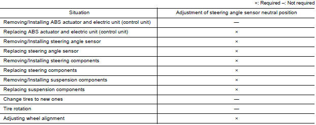
Refer to the table below to determine if adjustment of steering angle sensor neutral position is required.
Work Procedure
ADJUSTMENT OF STEERING ANGLE SENSOR NEUTRAL POSITION
CAUTION: To adjust neutral position of steering angle sensor, make sure to use CONSULT.
(Adjustment cannot be done without CONSULT).
1.ALIGN THE VEHICLE STATUS
Stop vehicle with front wheels in straight-ahead position.
>> GO TO 2
2.PERFORM THE NEUTRAL POSITION ADJUSTMENT FOR THE STEERING ANGLE SENSOR
- On the CONSULT screen, touch "WORK SUPPORT" and "ST ANG SEN ADJUSTMENT" in order.
- Touch "START".CAUTION:Do not touch steering wheel while adjusting steering angle sensor.
- After approximately 10 seconds, touch "END".
NOTE: After approximately 60 seconds, it ends automatically.
- Turn ignition switch OFF, then turn it ON again.
CAUTION: Be sure to perform above operation.
>> GO TO 3
3.CHECK DATA MONITOR
- Run vehicle with front wheels in straight-ahead position, then stop.
- Select "DATA MONITOR". Then make sure "STR ANGLE SIG" is within 0+-2.5.
Is the steering angle within the specified range?
YES >> GO TO 4
NO >> Perform the neutral position adjustment for the steering angle sensor again, GO TO 1
4.ERASE THE SELF-DIAGNOSIS MEMORY
Erase the self-diagnosis memory of the ABS actuator and electric unit (control unit) and ECM.
- ABS actuator and electric unit (control unit): Refer to BRC "CONSULT Function (ABS)".
- ECM: Refer to EC "CONSULT Function".
Are the memories erased?
YES >> Inspection End
NO >> Check the items indicated by the self-diagnosis.
DTC/CIRCUIT DIAGNOSIS
 Diagnosis and repair work flow
Work Flow OVERALL SEQUENCE DETAILED FLOW 1.COLLECT INFORMATION FROM THE CUSTOMER Get detailed information from the customer about the symptom (the condition and the environment when the in ...

Other materials:
Parking brake
WARNING
Be sure the parking brake is fully released
before driving. Failure to do so
can cause brake failure and lead to an
accident.
Do not release the parking brake from
outside the vehicle.
Do not use the shift lever in place of the
parking brake. When parking, be sure
the par ...
Readiness for inspection/maintenance (I/M) test
Due to legal requirements in some states and
Canadian Provinces, your vehicle may be required
to be in what is called the "ready condition"
for an Inspection/Maintenance (I/M) test of
the emission control system.
The vehicle is set to the "ready condition" when it
is driven through certain d ...
Categories
- Manuals Home
- Nissan Versa Owners Manual
- Nissan Versa Service Manual
- Video Guides
- Questions & Answers
- External Resources
- Latest Updates
- Most Popular
- Sitemap
- Search the site
- Privacy Policy
- Contact Us

0.0045