Nissan Versa (N17): Air cleaner filter
Exploded View
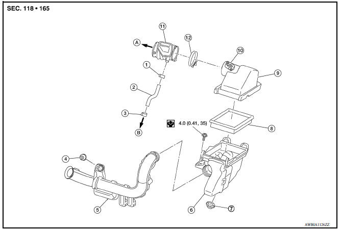
1. Clamp 2. PCV hose 3. Clamp 4. Mount rubber 5. Air duct (inlet) 6. Air cleaner body 7. Grommet 8. Air cleaner filter 9. Air cleaner cover 10. Mass air flow sensor 11. Air duct 12. Clamp
Removal and Installation
REMOVAL
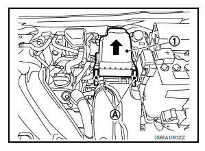
1. Unhook clips (A) and pull the air cleaner cover upward (1).
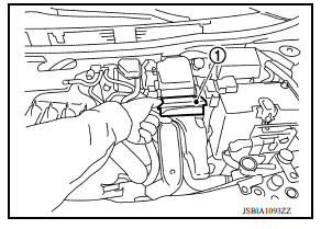
2. Remove the air cleaner filter (1) from the air cleaner body.
INSTALLATION
Installation is in the reverse order of removal.
NOTE:
Check that the air cleaner filter is securely placed in the air cleaner body.
 Drive belt
Exploded View 1. Generator 2. Water pump 3. Crankshaft pulley 4. A/C compressor (with A/C models) Idler pulley (without A/C models) 5. Idler pulley 6. Drive belt ...
Spark plug
Exploded View 1. Ignition coil 2. Spark plug Removal and Installation REMOVAL 1. Remove ignition coil. CAUTION: Do not drop or shock ignition coil. 2. Remove spark plug using a suitable tool. ...
Other materials:
Bluetooth Hands-Free Phone System without Navigation System (Type A) (if so
equipped)
WARNING
Use a phone after stopping your vehicle
in a safe location. If you have to use a
phone while driving, exercise extreme
caution at all times so full attention may
be given to vehicle operation.
If you are unable to devote full attention
to vehicle operation while talking on
...
Power steering fluid
Check the fluid level in the reservoir.
The fluid level should be checked when the fluid
is cold at fluid temperatures of 32 to 86ºF (0 to
30ºC). The fluid level can be checked with the
level gauge which is attached to the cap. To
check the fluid level, remove the cap. The fluid ...
Categories
- Manuals Home
- Nissan Versa Owners Manual
- Nissan Versa Service Manual
- Video Guides
- Questions & Answers
- External Resources
- Latest Updates
- Most Popular
- Sitemap
- Search the site
- Privacy Policy
- Contact Us

0.0058