
Nissan Versa (N17): Air pressure monitor
AIR PRESSURE MONITOR : CONSULT Function (BCM - AIR PRESSURE MONITOR)
NOTE: The Signal Tech II Tool (J-50190) can be used to perform the following functions. Refer to the Signal Tech II User Guide for additional information.
- Activate and display TPMS transmitter IDs
- Display tire pressure reported by the TPMS transmitter
- Read TPMS DTCs
- Register TPMS transmitter IDs
- Test remote keyless entry keyfob relative signal strength
SELF DIAGNOSTIC RESULT
NOTE: Before performing self diagnostic result, be sure to register the ID, or else the actual malfunction may be different from that displayed on CONSULT.
Refer to BCS "DTC Index".
DATA MONITOR
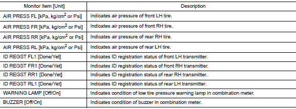
ACTIVE TEST

WORK SUPPORT
| Support Item | Description |
| ID READ | The registered ID number is displayed. |
| ID REGIST | Refer to WT "Description". |
ECU DIAGNOSIS INFORMATION
BCM
List of ECU Reference
| ECU | Reference |
| BCM (with Intelligent Key system) | BCS "Reference Value" |
| BCS "Fail-safe" | |
| BCS "DTC Inspection Priority Chart" | |
| BCS "DTC Index" | |
| BCM (without Intelligent Key system) | BCS "Reference Value" |
| BCS "Fail-safe" | |
| BCS "DTC Inspection Priority Chart" | |
| BCS "DTC Index" |
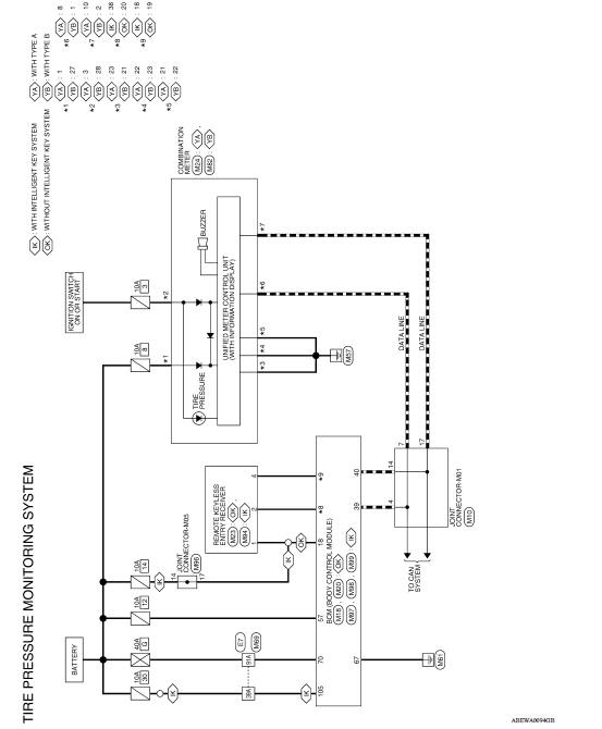
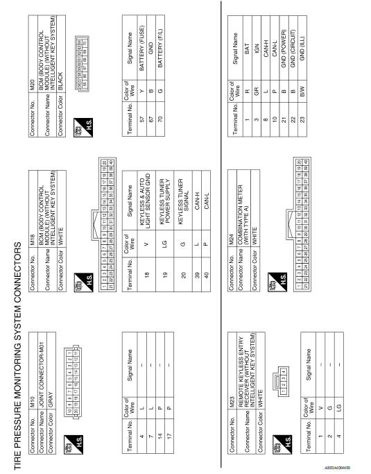
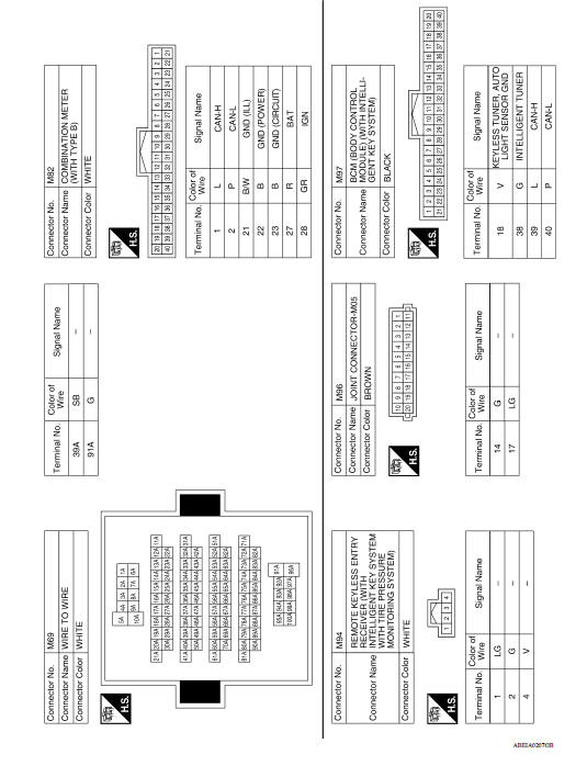
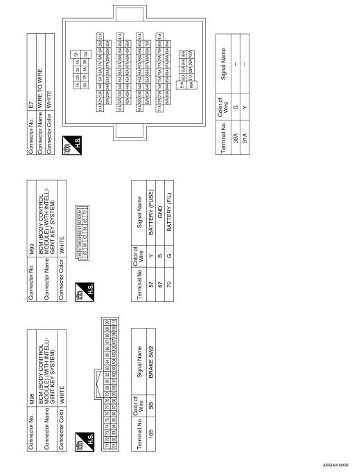
WIRING DIAGRAM
TIRE PRESSURE MONITORING SYSTEM
Wiring Diagram
BASIC INSPECTION
 Air pressure monitor
AIR PRESSURE MONITOR : CONSULT Function (BCM - AIR PRESSURE MONITOR) NOTE: The Signal Tech II Tool (J-50190) can be used to perform the following functions. Refer to the Signal Tech II User Gui ...
Diagnosis and repair work flow
Work Flow NOTE: The Signal Tech II Tool (J-50190) can be used to perform the following functions. Refer to the Signal Tech II User Guide for additional information. Activate and display TPMS ...
Other materials:
Precautions
Precaution for Supplemental Restraint System
(SRS) "AIR BAG" and "SEAT BELT PRE-TENSIONER"
The Supplemental Restraint System such as "AIR BAG" and "SEAT BELT PRE-TENSIONER",
used along
with a front seat belt, helps to reduce the risk or severity of injury to the
driver and ...
P0711 Transmission fluid temperature
sensor A
DTC Logic
DTC DETECTION LOGIC
DTC
Trouble diagnosis name
DTC detection condition
Possible causes
P0711
Transmission Fluid Temperature
Sensor A Circuit Range/
Performance
Under the following diagnosis conditions, CVT
fluid temperature does not rise to 10C (5 ...
Categories
- Manuals Home
- Nissan Versa Owners Manual
- Nissan Versa Service Manual
- Video Guides
- Questions & Answers
- External Resources
- Latest Updates
- Most Popular
- Sitemap
- Search the site
- Privacy Policy
- Contact Us

0.0086