Nissan Versa (N17): Audio unit
Exploded View
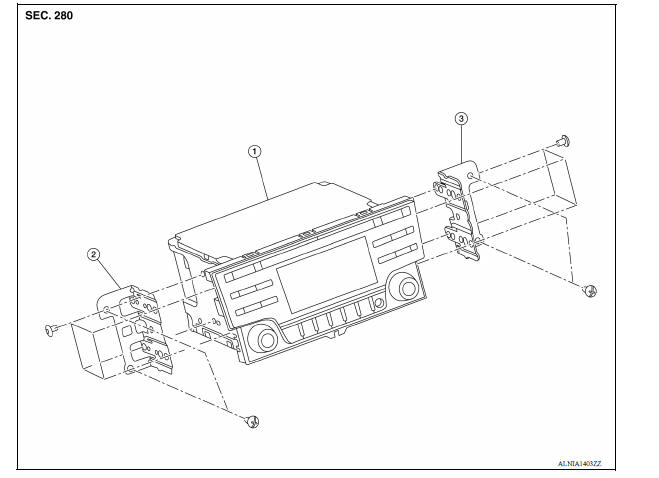
1. Audio unit 2. Audio unit bracket (LH) 3. Audio unit bracket (RH)
Removal and Installation
REMOVAL
1. Disconnect the negative battery terminal. Refer to PG "Removal and Installation".
2. Remove cluster lid C. Refer to IP "Removal and Installation".
3. Remove the audio unit screws, then pull out the audio unit.
4. Disconnect the harness connectors from the audio unit and remove.
INSTALLATION
Installation is in the reverse order of removal.
 Normal operating condition
Description RELATED TO NOISE The majority of the audio concerns are the result of outside causes (bad CD, electromagnetic interference, etc.). The following noise results from variations in fi ...
Front door speaker
Removal and Installation REMOVAL 1. Remove the front door finisher. Refer to INT "Removal and Installation". 2. Remove the front door speaker screws (A). 3. Disconnect the harness connec ...
Other materials:
Engine stand setting
Setting
NOTE:
The following procedures explain how to disassemble the engine with the engine
stand fastened to the bell
housing. Some steps may be different if using a different type of engine stand.
1. Install engine to engine stand:
a. Rem ...
U0073 Communication bus a off
DTC Logic
DTC
Trouble diagnosis name
DTC detecting condition
Possible causes
U0073
Control Module Communication
Bus "A" Off
When the ignition switch is ON,
TCM detects a bus-off error
continuously for 2 seconds or
more.
Harness or connector
(CA ...
Categories
- Manuals Home
- Nissan Versa Owners Manual
- Nissan Versa Service Manual
- Video Guides
- Questions & Answers
- External Resources
- Latest Updates
- Most Popular
- Sitemap
- Search the site
- Privacy Policy
- Contact Us

0.0053