Nissan Versa (N17): BCM Branch line circuit
Diagnosis Procedure
1.CHECK CONNECTOR
1. Turn the ignition switch OFF.
2. Disconnect the battery cable from the negative terminal.
3. Check the terminals and connectors of the BCM for damage, bend and loose connection (unit side and connector side).
Is the inspection result normal?
YES >> GO TO 2.
NO >> Repair the terminal and connector.
2.CHECK HARNESS FOR OPEN CIRCUIT
1. Disconnect the connector of BCM.
2. Check the resistance between the BCM harness connector terminals.
- Models with Intelligent Key system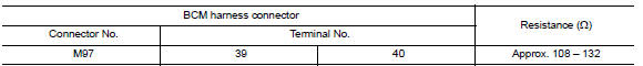
- Models without Intelligent Key system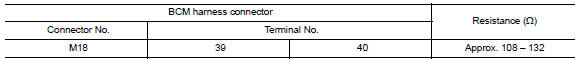
Is the measurement value within the specification?
YES >> GO TO 3.
NO >> Repair the BCM branch line.
3.CHECK POWER SUPPLY AND GROUND CIRCUIT
Check the power supply and the ground circuit of the BCM. Refer to the following.
- Models with Intelligent Key system: BCS "Diagnosis Procedure"
- Models without Intelligent Key system: BCS "Diagnosis Procedure"
Is the inspection result normal?
YES (Present error)>>Replace the BCM. Refer to the following.
- Models with Intelligent Key system: BCS "Removal and Installation"
- Models without Intelligent Key system: BCS "Removal and Installation"
YES (Past error)>>Error was detected in the BCM branch line.
NO >> Repair the power supply and the ground circuit.
 STRG Branch line circuit
Diagnosis Procedure 1.CHECK CONNECTOR 1. Turn the ignition switch OFF. 2. Disconnect the battery cable from the negative terminal. 3. Check the terminals and connectors of the steering angle sen ...
CAN Communication circuit
Diagnosis Procedure 1.CONNECTOR INSPECTION 1. Turn the ignition switch OFF. 2. Disconnect the battery cable from the negative terminal. 3. Disconnect all the unit connectors on CAN communication ...
Other materials:
Car phone or CB radio
When installing a CB, ham radio or car phone in
your vehicle, be sure to observe the following
precautions; otherwise, the new equipment may
adversely affect the engine control system and
other electronic parts.
WARNING
A cellular phone should not be used for
any purpose while driving so ...
Emission control system warranty
Your NISSAN vehicle is covered by the following
emission warranties:
For USA
1. Emission Defects Warranty
2. Emissions Performance Warranty
Details of this warranty may be found with other
vehicle warranties in your Warranty Information
Booklet which comes with your NISSAN vehicle.
If you ...
Categories
- Manuals Home
- Nissan Versa Owners Manual
- Nissan Versa Service Manual
- Video Guides
- Questions & Answers
- External Resources
- Latest Updates
- Most Popular
- Sitemap
- Search the site
- Privacy Policy
- Contact Us

0.0045