Nissan Versa (N17): Blower fan on signal
Component Function Check
1.CHECK BLOWER FAN ON SIGNAL
With CONSULT
- Turn ignition switch ON.
- Select "AIR CONDITIONER" of "BCM" using CONSULT.
- Select "FAN ON SIG" in "DATA MONITOR" mode, and check status under the
following condition.
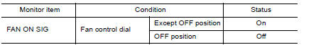
Is the inspection result normal?
YES >> Inspection End.
NO >> Refer to HAC "Diagnosis Procedure".
Diagnosis Procedure
Regarding Wiring Diagram information, refer to HAC "Wiring Diagram" or HAC "Wiring Diagram".
1.CHECK BLOWER FAN ON SIGNAL
- Turn ignition switch OFF.
- Disconnect front air control harness connector.
- Turn ignition switch ON.
- Check output waveform between front air control and ground with using
oscilloscope.
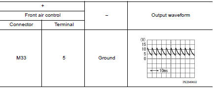
Is the inspection result normal?
YES >> Replace front air control. Refer to HAC "Removal and Installation".
NO >> GO TO 2.
2.CHECK BLOWER FAN ON SIGNAL CIRCUIT FOR OPEN
- Turn ignition switch OFF.
- Disconnect BCM connector.
- Check continuity front air control harness connector and BCM harness
connector.
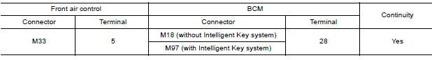
Is the inspection result normal?
YES >> GO TO 3.
NO >> Repair harness or connector.
3.CHECK BLOWER FAN ON SIGNAL CIRCUIT FOR SHORT
Check continuity between front air control harness connector and ground.
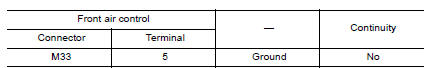
Is the inspection result normal?
YES >> Replace BCM. Refer to BCS "Removal and Installation" or BCS "Removal and Installation".
NO >> Repair harness or connector.
 A/C On signal
Component Function Check 1.CHECK A/C ON SIGNAL With CONSULT Turn ignition switch ON. Operate front blower motor. Select "AIR CONDITIONER" of "BCM" using CONSULT. Select "AIR COND SW" in ...
A/C Indicator
Diagnosis Procedure Regarding Wiring Diagram information, refer to HAC "Wiring Diagram" or HAC "Wiring Diagram". 1.CHECK A/C INDICATOR POWER SUPPLY Turn ignition switch O ...
Other materials:
Front stabilizer
Exploded View
1. Stabilizer bar 2. Stabilizer clamp 3. Stabilizer bushing
4. Stabilizer connecting rod 5. Strut assembly 6. Front suspension member
Front
Removal and Installation
REMOVAL
Remove wheel and tire assemblies using power tool. Refer to WT
"Adjustment".
Remove ...
Diagnosis and repair work flow
Work Flow
NOTE:
The Signal Tech II Tool (J-50190) can be used to perform the following
functions. Refer to the Signal Tech II User Guide for additional information.
Activate and display TPMS transmitter IDs
Display tire pressure reported by the TPMS transmitter
Read TPMS DTCs
Register ...
Categories
- Manuals Home
- Nissan Versa Owners Manual
- Nissan Versa Service Manual
- Video Guides
- Questions & Answers
- External Resources
- Latest Updates
- Most Popular
- Sitemap
- Search the site
- Privacy Policy
- Contact Us

0.0049