Nissan Versa (N17): Rear combination lamp
Exploded View
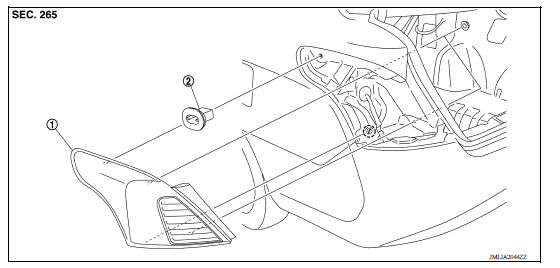
1. Rear combination lamp 2. Grommet
 Clip
Clip
Removal and Installation
REMOVAL
1. Remove trunk rear finisher. Refer to. INT "TRUNK REAR PLATE : Removal and Installation".
2. Remove rear combination lamp nuts.
3. Disengage the locating pin (A) of the rear combination lamp using a suitable tool (B) at the gap between the rear combination lamp and rear fender.
CAUTION: Apply protective tape (C) on body to protect the painted surface from damage.
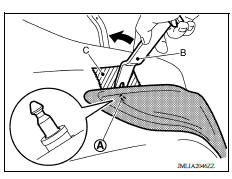
4. Disconnect the harness connectors from the rear combination lamp and remove.
INSTALLATION
Installation is in the reverse order of removal.
Disassembly and Assembly
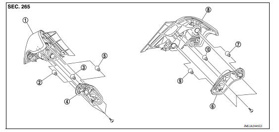
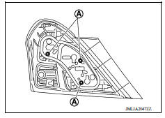
1. Rear combination lamp (RH) 2. Stop/tail lamp bulb (RH) 3. Back-up lamp bulb (RH) 4. Bulb holder (RH) 5. Rear turn signal lamp bulb (RH) 6. Bulb holder (LH) 7. Stop/tail lamp bulb (LH) 8. Rear combination lamp (LH) 9. Back-up lamp bulb (LH) 10. Rear turn signal lamp bulb (LH)
Bulb Replacement
WARNING: Do not touch bulb with your hand while it is on or right after being turned off. Burning may result.
CAUTION:
- Disconnect the battery negative terminal or remove power circuit fuse while performing the operation.
- Do not touch the glass surface of the bulb with bare hands or allow oil or grease to get on it to prevent damage to the bulb.
- Do not leave bulb out of lamp reflector for a long time because dust, moisture smoke, etc. may affect the performance of lamp. When replacing bulb, be sure to replace it with new one.
STOP/TAIL LAMP BULB
Removal
1. Remove rear combination lamp. Refer to EXL "Removal and Installation".
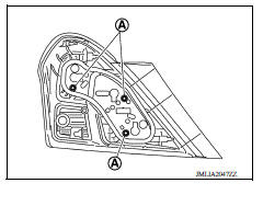
2. Remove screws (A) and the bulb holder.
3. Rotate stop/tail lamp bulb counterclockwise and remove.
Installation
Installation is in the reverse order of removal.
CAUTION: After installing the bulb, install the back cover and the bulb socket securely for watertightness.
REAR TURN SIGNAL LAMP BULB
Removal
1. Remove rear combination lamp. Refer to EXL "Removal and Installation".
2. Remove screws (A) and the bulb holder.
3. Rotate rear turn signal lamp bulb counterclockwise and remove
Installation
Installation is in the reverse order of removal.
CAUTION: After installing the bulb, install the cover and the bulb socket securely for watertightness.
BACK-UP LAMP BULB
Removal
1. Remove rear combination lamp. Refer to EXL "Removal and Installation".
2. Remove screws (A) and the bulb holder.
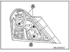
3. Rotate back-up lamp bulb counterclockwise and remove.
Installation
Installation is in the reverse order of removal.
CAUTION: After installing the bulb, install the cover and the bulb socket securely for watertightness.
 Hazard switch
Exploded View 1. Cluster lid C 2. Hazard switch Pawl Removal and Installation REMOVAL 1. Remove the cluster lid C. Refer to IP "Removal and Installation". 2. While pressing pawls, ...
High-mounted stop lamp
Exploded View Rear Spoiler 1. Rear spoiler 2. High-mounted stop lamp assembly Rear Parcel Shelf 1. Rear parcel shelf finisher 2. High-mounted stop lamp socket 3. High-mounted stop lamp b ...
Other materials:
Jump starting
To start your engine with a booster battery, the
instructions and precautions below must be followed.
WARNING
If done incorrectly, jump starting can
lead to a battery explosion, resulting in
severe injury or death. It could also
damage your vehicle.
Explosive hydrogen gas is always pre ...
Shift position indicator circuit
Component Parts Function Inspection
1.CHECK SHIFT POSITION INDICATOR
Start the engine.
Shift selector lever.
Check that the selector lever position and the shift position indicator
on the combination meter are identical.
Is the inspection result normal?
YES >> INSPECTION END
N ...
Categories
- Manuals Home
- Nissan Versa Owners Manual
- Nissan Versa Service Manual
- Video Guides
- Questions & Answers
- External Resources
- Latest Updates
- Most Popular
- Sitemap
- Search the site
- Privacy Policy
- Contact Us

0.005