Nissan Versa (N17): C1116 Stop lamp switch
DTC Logic
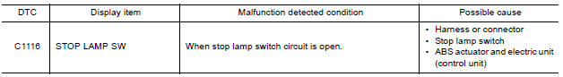
DTC DETECTION LOGIC
DTC CONFIRMATION PROCEDURE
1.CHECK SELF-DIAGNOSIS RESULTS
Check the self-diagnosis results.

Is above displayed on the self-diagnosis display?
YES >> Proceed to diagnosis procedure. Refer to BRC "Diagnosis Procedure".
NO >> Inspection End.
Diagnosis Procedure
Regarding Wiring Diagram information, refer to BRC "Wiring Diagram".
1.CONNECTOR INSPECTION
- Disconnect stop lamp switch connector and ABS actuator and electric unit (control unit) connector.
- Check terminals for deformation, disconnection, looseness or damage.
Is the inspection result normal?
YES >> GO TO 2
NO >> Repair or replace as necessary.
2.CHECK STOP LAMP SWITCH CIRCUIT
- Connect stop lamp switch connector.
- Check voltage between ABS actuator and electric unit (control unit)
connector E33 terminal 30 and
ground.
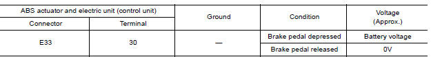
Is the inspection result normal?
YES >> Replace ABS actuator and electric unit (control unit). Refer to BRC "Removal and Installation".
NO >> GO TO 3
3.CHECK STOP LAMP SWITCH CIRCUIT FOR OPEN
- Disconnect stop lamp switch connector.
- Check continuity between ABS actuator and electric unit (control unit)
connector E33 terminal 30 and stop
lamp switch connector E13 (with CVT) or E57 (with M/T) terminal 2.
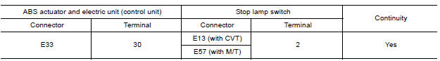
Is the inspection result normal?
YES >> GO TO 4.
NO >> Repair or replace as necessary.
4.CHECK STOP LAMP SWITCH CIRCUIT FOR SHORT
Check continuity between ABS actuator and electric unit (control unit)
connector E33 terminal 30 and ground.
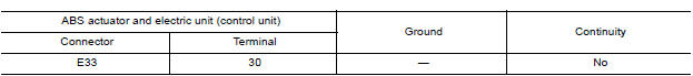
Is the inspection result normal?
YES >> Replace stop lamp switch.
NO >> Repair harness or connectors.
 C1115 ABS Sensor [abnormal signal]
Other materials:
EVAP control system pressure sensor
Exploded View
1. EVAP control system pressure sensor 2. O-ring 3. EVAP canister
Removal and Installation
NOTE:
The EVAP canister system pressure sensor can be removed without removing the
EVAP canister.
REMOVAL
Remove the EVAP canister protector cover.
Disconnect EVAP canister purg ...
Lock-up control
Lock-up control : system diagram
Lock-up control : system description
The torque converter clutch piston in the torque converter is engaged to
eliminate torque converter slip to
increase power transmission efficiency.
The torque converter clutch control valve operation is controlle ...
Categories
- Manuals Home
- Nissan Versa Owners Manual
- Nissan Versa Service Manual
- Video Guides
- Questions & Answers
- External Resources
- Latest Updates
- Most Popular
- Sitemap
- Search the site
- Privacy Policy
- Contact Us

0.0061