Nissan Versa (N17): Coil spring
Exploded View
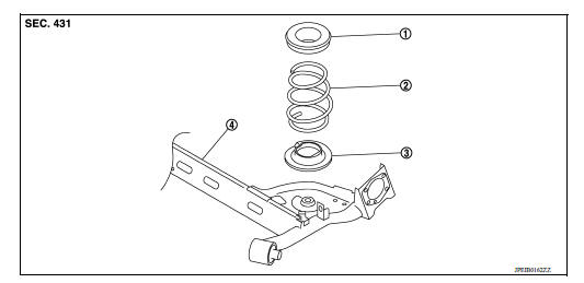
1. Upper rubber seat 2. Coil spring 3. Lower rubber seat 4. Rear suspension beam
Removal and Installation
REMOVAL
- Remove the wheel and tire assemblies using power tool. Refer to WT "Adjustment".
- Position a suitable jack under rear suspension beam.
CAUTION:
- Place the jack in the center of the suspension beam.
- Do not damage the suspension beam with jack.
- Remove the lower shock absorber bolts. Refer to RSU "Removal and Installation".
- Slowly lower jack, then remove upper rubber seat, coil spring and lower rubber seat from rear suspension beam.
INSTALLATION
Installation is in the reverse order of removal.
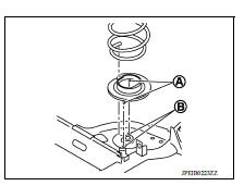
- Install the lower rubber seat (A) to the rear suspension beam mounting hole (B).
- Match up lower rubber seat indentions and rear suspension beam grooves and attach.
Inspection
INSPECTION AFTER REMOVAL
Check rubber seat and coil spring for deformation, crack, and damage. Replace it if necessary.
INSPECTION AFTER INSTALLATION
Check wheel alignment. Refer to RSU "Inspection".
 Rear shock absorber
Exploded View 1. Piston rod lock nut 2. Washer 3. Bushing 4. Distance tube 5. Bound bumper cover 6. Bound bumper 7. Shock absorber assembly 8. Rear suspension beam ...
Rear suspension beam
Exploded View 1. Rear suspension beam Removal and Installation REMOVAL Remove the wheel and tire assemblies using power tool. Refer to WT "Adjustment". Remove wheel sensor ...
Other materials:
Sun visors
1. To block glare from the front, swing down
the sun visor 1 .
2. To block glare from the side, remove the sun
visor from the center mount and swing the
visor to the side 2 .
3. Slide the extension 3 sun visor in or out as
needed.
CAUTION
Do not store the sun visor before returning
...
Engine cooling system
The engine cooling system is filled at the factory
with a pre-diluted mixture of 50% Genuine
NISSAN Long Life Antifreeze/Coolant (blue) and
50% water to provide year-round antifreeze and
coolant protection. The antifreeze solution contains
rust and corrosion inhibitors. Additional engine
cooli ...
Categories
- Manuals Home
- Nissan Versa Owners Manual
- Nissan Versa Service Manual
- Video Guides
- Questions & Answers
- External Resources
- Latest Updates
- Most Popular
- Sitemap
- Search the site
- Privacy Policy
- Contact Us

0.0059