Nissan Versa (N17): Combination switch
Exploded View
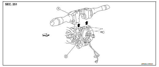
1. Combination switch 2. Combination switch harness connector  Front
Front
Removal and Installation
1. Remove the steering wheel. Refer to ST "Removal and Installation".
2. Remove the steering column cover. Refer to IP "Removal and Installation".
3. Remove the combination switch screws.
4. Disconnect the harness connector from the combination switch.
5. Remove the combination switch by lifting upward.
INSTALLATION
Installation is in the reverse order of removal.
 BCM (Body control module)
Removal and Installation CAUTION: Before replacing BCM, perform "READ CONFIGURATION" to save or print current vehicle specification. Refer to BCS "ADDITIONAL SERVICE WHEN REPLACING CONTR ...
Precautions
Precautions for Trouble Diagnosis CAUTION: Follow the instructions listed below. Failure to do this may cause damage to parts: Never apply 7.0 V or more to the measurement terminal. Use a ...
Other materials:
Secondary speed sensor
Exploded View
1. Transaxle assembly 2. O-ring 3. Secondary speed sensor
Front :
Genuine NISSAN CVT Fluid NS-3
Removal and Installation
REMOVAL
Remove the front LH wheel and tire. Refer to WT "Adjustment".
Remove the fender protector (LH). Refer to EXT "Removal and
...
U1000 CAN Comm
Description
Refer to LAN "CAN COMMUNICATION SYSTEM : System Description".
DTC Logic
DTC DETECTION LOGIC
NOTE:
U1000 can be set if a module harness was disconnected and reconnected, perhaps
during a repair. Confirm
that there are actual CAN diagnostic symptoms and a present DTC ...
Categories
- Manuals Home
- Nissan Versa Owners Manual
- Nissan Versa Service Manual
- Video Guides
- Questions & Answers
- External Resources
- Latest Updates
- Most Popular
- Sitemap
- Search the site
- Privacy Policy
- Contact Us

0.0068