Nissan Versa (N17): System
Body control system
BODY CONTROL SYSTEM : System Description
OUTLINE
- BCM (Body Control Module) controls the various electrical components. It inputs the information required to the control from CAN communication and the signal received from each switch and sensor.
- BCM has combination switch reading function for reading the operation
status of combination switches (light,
turn signal, wiper and washer) in addition to a function for controlling the
operation of various electrical components.
It also has the signal transmission function as the passed point of signal and the power saving control function that reduces the power consumption with the ignition switch OFF.
- BCM is equipped with the diagnosis function that performs the diagnosis with CONSULT and various settings.
BCM CONTROL FUNCTION LIST
| System | Reference | |
| Combination switch reading system | BCS "COMBINATION SWITCH READING SYSTEM : System Description" | |
| Signal buffer system | BCS "SIGNAL BUFFER SYSTEM : System Description" | |
| Power consumption control system | BCS "POWER CONSUMPTION CONTROL SYSTEM : System Description" | |
| Headlamp system | EXL "HEADLAMP SYSTEM : System Description" | |
| Daytime light system | EXL "WITH DAYTIME LIGHT SYSTEM : System Description" | |
| Turn signal and hazard warning lamp system | EXL "TURN SIGNAL AND HAZARD WARNING LAMP SYSTEM : System Description" | |
| Parking, license plate and tail lamps system | EXL "PARKING, LICENSE PLATE AND TAIL LAMP SYSTEM : System Description" | |
| Front fog lamp system | EXL "FRONT FOG LAMP SYSTEM : System Description" | |
| Exterior lamp battery saver system | EXL "HEADLAMP SYSTEM : System Description" | |
| Interior room lamp control system | INL "INTERIOR ROOM LAMP CONTROL SYSTEM : System Description" | |
| Interior room lamp battery saver system | INL "INTERIOR ROOM LAMP CONTROL SYSTEM : System Description" | |
| Front wiper and washer system | WW "System Description" | |
| Rear window defogger system | DEF "System Description" | |
| Manual air conditioning system | HAC "MANUAL AIR CONDITIONING SYSTEM : System Description" | |
| Warning chime system | WCS "WARNING CHIME SYSTEM : System Description" | |
| Power door lock system | DLK "System Description" | |
| Trunk lid opener system | DLK "System Description" | |
| Nissan vehicle immobilizer system (NVIS) | SEC "NISSAN ANTI-THEFT SYSTEM : System Description" | |
| Vehicle security system | SEC "VEHICLE SECURITY SYSTEM : System Description" | |
| Panic alarm | SEC "VEHICLE SECURITY SYSTEM : System Description" | |
| Intelligent Key system/engine start system | Door lock function | DLK "DOOR LOCK FUNCTION : System Description" |
| Trunk open function | DLK "TRUNK OPEN FUNCTION : System Description" | |
| Warning function | DLK "WARNING FUNCTION : System Description" | |
| Key reminder function | DLK "KEY REMINDER FUNCTION : System Desciption" | |
| Engine start function | SEC "INTELLIGENT KEY SYSTEM/ENGINE START FUNCTION : System Description" | |
| Power window system | PWC "System Description" | |
| RAP (retained accessory power) system | BCS "RETAINED PWR : CONSULT Function (BCM - RETAINED PWR)" | |
| TPMS (tire pressure monitoring system) | WT "TIRE PRESSURE MONITORING SYSTEM : System Description" | |
Combination switch reading system
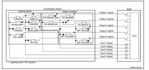
COMBINATION SWITCH READING SYSTEM : System Diagram
COMBINATION SWITCH READING SYSTEM : System Description
OUTLINE
- BCM reads the status of the combination switch (light, turn signal, wiper and washer) and recognizes the status of each switch.
- BCM has a combination of 5 output terminals (OUTPUT 1 - 5) and 5 input terminals (INPUT 1 - 5). It reads a maximum of 20 switch states.
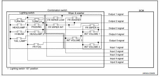
COMBINATION SWITCH MATRIX
Combination switch circuit
Combination switch INPUT-OUTPUT system list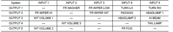
COMBINATION SWITCH READING FUNCTION
Description
- BCM reads the status of the combination switch at 10 ms intervals
normally.
NOTE: BCM reads the status of the combination switch at 60 ms intervals when BCM is controlled at low power consumption control mode.
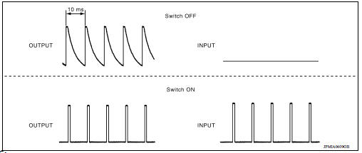
- BCM operates as follows and judges the status of the combination switch.
- It operates the transistor on OUTPUT side in the following order: OUTPUT 1 → 2 → 3 → 4 → 5, and outputs voltage waveform.
- The voltage waveform of OUTPUT corresponding to the formed circuit is input into the interface on INPUT side if any (1 or more) switches are ON.
- It reads this change of the voltage as the status signal of the combination switch.
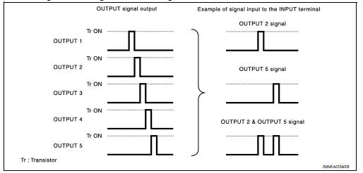
Operation Example
In the following operation example, the combination of the status signals of the combination switch is replaced as follows: INPUT 1 - 5 to "1 - 5" and OUTPUT 1 - 5 to "A - E".
Example 1: When a switch (TAIL LAMP) is turned ON
- The circuit between OUTPUT 4 and INPUT 5 is formed when the TAIL LAMP
switch is turned ON.
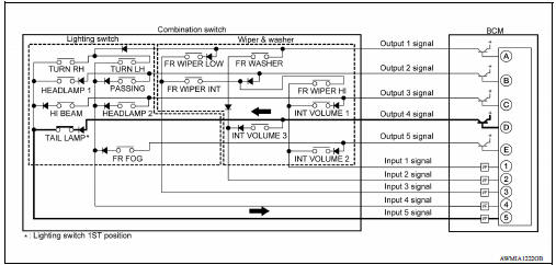
- BCM detects the combination switch status signal "5D" when the signal of OUTPUT 4 is input to INPUT 5.
- BCM judges that the TAIL LAMP switch is ON when the signal "5D" is detected.
Example 2: When some switches (TURN RH, TAIL LAMP) are turned ON
- The circuits between OUTPUT 1 and INPUT 5 and between OUTPUT 4 and INPUT 5 are formed when the
TURN RH switch and TAIL LAMP switch are turned ON.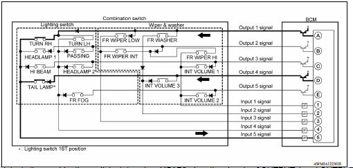
- BCM detects the combination switch status signal "5AD" when the signals of OUTPUT 1 and OUTPUT 4 are input to INPUT 5.
- BCM judges that the TURN RH switch and TAIL LAMP switch are ON when the signal "5AD" is detected.
WIPER INTERMITTENT DIAL POSITION
BCM judges the wiper intermittent dial 1 - 7 by the status of INT VOLUME 1, 2
and 3 switches.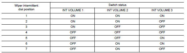
NOTE: For details of wiper intermittent dial position, refer to WW "System Description".
Signal buffer system
SIGNAL BUFFER SYSTEM : System Diagram
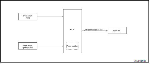
SIGNAL BUFFER SYSTEM : System Description
OUTLINE
BCM has the signal transmission function that outputs/transmits each input/received signal to each unit.
Signal transmission function list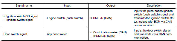
Power consumption control system
POWER CONSUMPTION CONTROL SYSTEM : System Diagram
POWER CONSUMPTION CONTROL SYSTEM : System Description
OUTLINE
- BCM incorporates a power saving control function that reduces the power consumption according to the vehicle status.
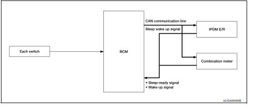
- BCM switches the status (control mode) by itself with the power saving control function. It performs the sleep request to each unit (IPDM E/R and combination meter) that operates with the ignition switch OFF.
Normal mode (wake-up)
- CAN communication is normally performed with other units
- Each control with BCM is operating properly
CAN communication sleep mode (CAN sleep)
- CAN transmission is stopped
- Control with BCM only is operating
Low power consumption mode (BCM sleep)
- Low power consumption control is active
- CAN transmission is stopped
LOW POWER CONSUMPTION CONTROL WITH BCM
BCM reduces the power consumption with the following operation in the low power consumption mode.
- The reading interval of each switch changes from 10 ms interval to 60 ms interval.
Sleep mode activation
- BCM receives the sleep-ready signal (ready) from IPDM E/R and combination meter via CAN communication.
- BCM transmits the sleep wake up signal (sleep) to each unit when all of the CAN sleep conditions are fulfilled.
- Each unit stops the transmission of CAN communication with the sleep wakeup signal. BCM is in CAN communication sleep mode.
- BCM is in the low power consumption mode and performs the low power consumption control when all of the BCM sleep conditions are fulfilled with CAN sleep condition.
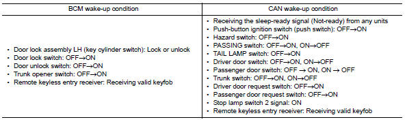
Sleep condition 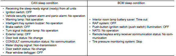
Wake-up operation
- BCM changes from the low power consumption mode to the CAN communication sleep mode when the any of the BCM wake-up conditions are fulfilled. Only the control with BCM is activated.
- BCM transmits the sleep wake up signal (wake up) to each unit when any of the CAN wake-up conditions are fulfilled. It changes from the low power consumption mode or the CAN communication sleep mode to the normal mode.
- Each unit starts the transmission of CAN communication with the sleep
wake up signal. In addition, the combination
meter transmits the wake up signal to BCM via CAN communication to report
the CAN communication
start.
 Precautions
Precaution for Supplemental Restraint System (SRS) "AIR BAG" and "SEAT BELT PRE-TENSIONER" The Supplemental Restraint System such as "AIR BAG" and "SEAT BELT PRE-TENSIONER", us ...
Diagnosis system (BCM)
COMMON ITEM COMMON ITEM : CONSULT Function (BCM - COMMON ITEM) APPLICATION ITEM CONSULT performs the following functions via CAN communication with BCM. SYSTEM APPLICATION BCM can perform the ...
Other materials:
Starting the engine (models without NISSAN Intelligent Key system)
1. Apply the parking brake.
2. Automatic Transmission / CVT models:
Move the shift lever to P (Park) or N (Neutral).
P (Park) is recommended.
The shift lever cannot be moved out of
P (Park) and into any of the other gear
positions if the ignition key is turned to
the OFF position or if ...
Brake pad
BRAKE PAD : Inspection and Adjustment
INSPECTION
Check brake pad wear thickness from an inspection hole on cylinder
body. Check using a scale if necessary.
Wear thickness : Refer to BR "Front Disc Brake".
ADJUSTMENT
Burnish contact surfaces between disc rotor and brake pads a ...
Categories
- Manuals Home
- Nissan Versa Owners Manual
- Nissan Versa Service Manual
- Video Guides
- Questions & Answers
- External Resources
- Latest Updates
- Most Popular
- Sitemap
- Search the site
- Privacy Policy
- Contact Us

0.0098