Nissan Versa (N17): Driver side door mirror defogger
Description
Heats the heating wire with the power supply from the rear window defogger relay to prevent the door mirror from fogging up.
Component Function Check
1. CHECK DOOR MIRROR DEFOGGER LH
Check that heating wire of door mirror defogger LH is heated when turning the rear window defogger switch ON.
Is the inspection result normal?
YES >> Door mirror defogger is OK.
NO >> Refer to DEF "Diagnosis Procedure".
Diagnosis Procedure
Regarding Wiring Diagram information, refer to DEF "Wiring Diagram".
1. CHECK POWER SUPPLY CIRCUIT
1. Turn ignition switch OFF.
2. Disconnect door mirror LH.
3. Turn ignition switch ON.
4. Check voltage between door mirror LH connector and ground.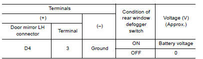
Is the inspection result normal?
YES >> GO TO 2
NO >> Repair or replace harness.
2. CHECK GROUND CIRCUIT
1. Turn ignition switch OFF.
2. Check continuity between door mirror LH connector and ground.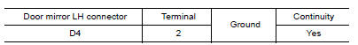
Is the inspection result normal?
YES >> GO TO 3
NO >> Repair or replace harness.
3. CHECK DOOR MIRROR DEFOGGER LH
Check door mirror defogger LH.
Refer to DEF "Component Inspection".
Is the inspection result normal?
YES >> GO TO 4
NO >> Replace door mirror. Refer to MIR "DOOR MIRROR ASSEMBLY : Removal and Installation".
4. CHECK INTERMITTENT INCIDENT
Check intermittent incident.
Refer to GI "Intermittent Incident".
Is the inspection result normal?
YES >> Check the following.
- Battery power supply circuit.
- Fuse block (J/B).
NO >> Repair or replace the malfunctioning parts.
Component Inspection
1. CHECK DOOR MIRROR DEFOGGER LH
1. Turn ignition switch OFF.
2. Disconnect door mirror LH.
3. Check continuity between door mirror terminals.
Is the inspection result normal?
YES >> Inspection End.
NO >> Replace door mirror LH. Refer to MIR "DOOR MIRROR ASSEMBLY : Removal and Installation".
 Rear window defogger power supply
and ground circuit
Rear window defogger power supply
and ground circuit
Description Heats the heating wire with the power supply from the rear window defogger relay to prevent the rear window from fogging up. ...
Passenger side door mirror defogger
Description Heats the heating wire with the power supply from the rear window defogger relay to prevent the door mirror from fogging up. ...
Other materials:
Hood hinge
HOOD HINGE : Removal and Installation
REMOVAL
Remove hood assembly. Refer to DLK "HOOD ASSEMBLY : Removal and
Installation".
Remove hood support rod and grommet. Refer to DLK "HOOD SUPPORT ROD : Removal
andInstallation".
Remove front fender. Refer to DLK "FRONT ...
Fender protector
Exploded View
1. Fender protector 2. J-nut Front
Removal and Installation
REMOVAL
1. Remove under cover. Refer to EXT"Removal and Installation".
2. Remove fender protector screws and clips.
3. Remove fender protector.
INSTALLATION
Installation is in the reverse order of removal ...
Categories
- Manuals Home
- Nissan Versa Owners Manual
- Nissan Versa Service Manual
- Video Guides
- Questions & Answers
- External Resources
- Latest Updates
- Most Popular
- Sitemap
- Search the site
- Privacy Policy
- Contact Us

0.0072