Nissan Versa (N17): Component parts
Component Parts Location
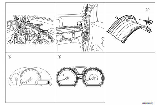
1 BCM (view with instrument panel removed) 2 Remote keyless entry receiver (view with instrument panel removed) 3 Transmitter 4 Combination meter (with type A) 5 Combination meter (with type B)
Component Description
|
Component parts |
Function |
| BCM | WT "BCM". |
| Remote keyless entry receiver | WT "Remote Keyless Entry Receiver". |
| Transmitter | WT "Transmitter". |
| Low tire pressure warning lamp | WT "TIRE PRESSURE MONITORING SYSTEM : System Description" |
| Combination meter | Transmits the vehicle speed signal via CAN communication to BCM. |
| Receives the low tire pressure warning lamp signal via CAN communication from BCM. |
BCM
The BCM reads the tire pressure signal received by the remote keyless entry receiver, and controls the low tire pressure warning lamp and the buzzer operations. It also has a self-diagnosis function to detect a system malfunction.
Remote Keyless Entry Receiver
The remote keyless entry receiver receives the tire pressure signal transmitted by the transmitter in each wheel.
Transmitter
A sensor-transmitter integrated with a valve is installed in each wheel, and transmits a detected tire pressure signal in the form of a radio wave. The radio signal is received by the remote keyless entry receiver.
Low Tire Pressure Warning Lamp
The combination meter receives tire pressure status from the BCM using CAN communication. When a low tire pressure condition is sensed by the BCM, the combination meter low tire pressure warning lamp is activated.
SYSTEM
 PRECAUTIONS
Precaution for Supplemental Restraint System (SRS) "AIR BAG" and "SEAT BELT PRE-TENSIONER" The Supplemental Restraint System such as "AIR BAG" and "SEAT BELT PRE-TENSIONER", us ...
Tire pressure monitoring system
TIRE PRESSURE MONITORING SYSTEM : System Diagram TIRE PRESSURE MONITORING SYSTEM : System Description The BCM has pressure judgment and trouble diagnosis functions. When the BCM detects ...
Other materials:
P0507 ISC system
Description
The ECM controls the engine idle speed to a specified level through the fine
adjustment of the air, which is let
into the intake manifold, by operating the electric throttle control actuator.
The operating of the throttle valve is
varied to allow for optimum control of the engine ...
Shift change control
Shift change control : system diagram
Shift change control : system description
The clutch is controlled with the optimum timing and oil pressure by the
engine speed, engine torque information,
etc.
Shift Change System Diagram
*1: Full phase real-time feedback control monitors m ...
Categories
- Manuals Home
- Nissan Versa Owners Manual
- Nissan Versa Service Manual
- Video Guides
- Questions & Answers
- External Resources
- Latest Updates
- Most Popular
- Sitemap
- Search the site
- Privacy Policy
- Contact Us

0.005