Nissan Versa (N17): Component parts
AUTOMATIC DOOR LOCK/UNLOCK FUNCTION
AUTOMATIC DOOR LOCK/UNLOCK FUNCTION : Component Parts Location
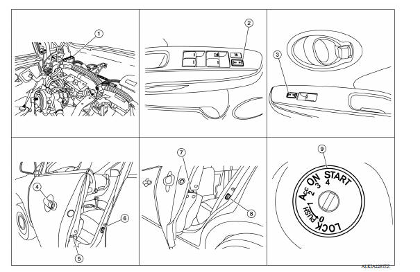
1. BCM (view with instrument panel removed) 2. Main power window and door lock/unlock switch 3. Power window and door lock/unlock switch RH 4. Front door lock key cylinder switch LH 5. Front door lock actuator LH (RH similar) 6. Front door switch LH (RH similar) 7. Rear door lock actuator LH (RH similar) 8. Rear door switch LH (RH similar) 9. Key switch
AUTOMATIC DOOR LOCK/UNLOCK FUNCTION
: Component Description 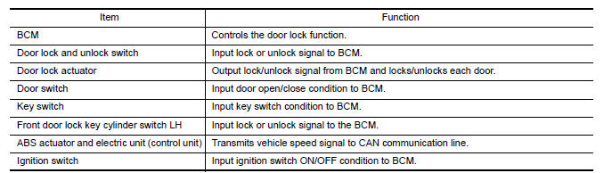
POWER DOOR LOCK SYSTEM
POWER DOOR LOCK SYSTEM : Component Parts Location
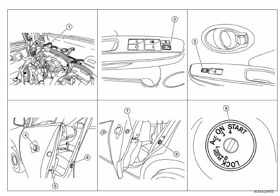
1. BCM (view with instrument panel removed) 2. Main power window and door lock/unlock switch 3. Power window and door lock/unlock switch RH 4. Front door lock key cylinder switch LH 5. Front door lock actuator LH (RH similar) 6. Front door switch LH (RH similar) 7. Rear door lock actuator LH (RH similar) 8. Rear door switch LH (RH similar) 9. Key switch
POWER DOOR LOCK SYSTEM :
Component Description 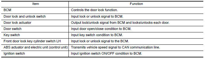
REMOTE KEYLESS ENTRY SYSTEM
REMOTE KEYLESS ENTRY SYSTEM : Component Parts Location
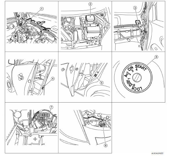
1. BCM (view with instrument panel removed) 2. IPDM E/R 3. Remote keyless entry receiver (view with instrument panel removed) 4. Front door switch LH (RH similar) 5. Rear door switch LH (RH similar) 6. Key switch 7. Horn relay (view with IPDM E/R removed) 8. Horn
REMOTE KEYLESS ENTRY SYSTEM :
Component Description 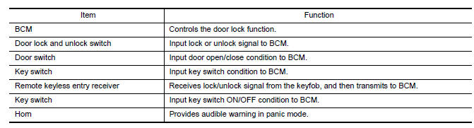
TRUNK LID OPENER SYSTEM
TRUNK LID OPENER SYSTEM : Component Parts Location
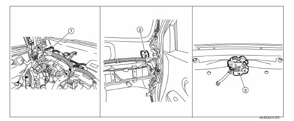
1. BCM (view with instrument panel removed) 2. Remote keyless entry receiver (view with instrument panel removed) 3. Trunk lid opener actuator
TRUNK LID OPENER SYSTEM : Component Description 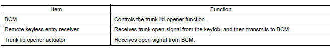
SYSTEM
 Precautions
Automatic door lock/unlock function
AUTOMATIC DOOR LOCK/UNLOCK FUNCTION : System Diagram AUTOMATIC DOOR LOCK/UNLOCK FUNCTION : System Description DOOR LOCK FUNCTION The door lock and unlock switch (driver side) is built i ...
Other materials:
Maintenance under severe operating conditions
The maintenance intervals shown on the preceding pages are for normal
operating conditions. If the vehicle is mainly operated under severe driving
conditions as shown below, more frequent maintenance must be performed on the
following items as shown in the table.
Severe driving conditions
...
Exhaust valve timing control
Exhaust valve timing control : system diagram
Exhaust valve timing control : system description
INPUT/OUTPUT SIGNAL CHART
Sensor
Input signal to ECM
ECM function
Actuator
Crankshaft position sensor (POS)
Engine speed*1
Piston position
Exhaust valve timing c ...
Categories
- Manuals Home
- Nissan Versa Owners Manual
- Nissan Versa Service Manual
- Video Guides
- Questions & Answers
- External Resources
- Latest Updates
- Most Popular
- Sitemap
- Search the site
- Privacy Policy
- Contact Us

0.0053