Toyota
Nissan Versa
 Sedan Service Manual
Transmission & driveline » Transaxle & transmission (TM)
Consult function

APPLICATION ITEMS

Diagnostic test mode Function
Work Support This mode enables a technician to adjust some devices faster and more accurately.
Self Diagnostic Results Retrieve DTC from ECU and display diagnostic items.
Data Monitor Monitor the input/output signal of the control unit in real time.
CAN Diagnosis This mode displays a network diagnosis result about CAN by a diagram.
CAN Diagnostic Support Monitor It monitors the starts of CAN communication.
DTC Work Support DTC reproduction procedure can be performed speedily and precisely.
ECU Identification Display the ECU identification number (part number etc.) of the selected system.
CALIB DATA The calibration data status of TCM can be checked

WORK SUPPORT

Item name

Description

ERASE CALIBRATION DATA Erases the "CALIBRATION DATA" stored by the TCM.
ERASE LEARNING VALUE Erases the "LEARNING VALUE" stored by the TCM.
ERASE MEMORY DATA Erases both the "CALIBRATION DATA" and "LEARNING VALUE".

SELF DIAGNOSTIC RESULTS

Refer to TM, "DTC Index".

DTC at 1st trip and method to read DTC

  • DTC (P0705, P0711, P0720, etc.) is specified by SAE J2012/ISO 15031-6.
  • DTC and DTC at 1st trip are displayed on "Self Diagnostic results" of CONSULT. " Timing" shows current malfunction or malfunction in the past.

    If current DTC is detected, "timing" is "present". If the "timing" is "memorized", it is the malfunction occurred in the past. According to "ignition counter" in "FFD", the number (trip) of operation without malfunction of the DTC can be checked.

  • When the DTC at the 1st trip is detected, the "timing" is displayed as "1t".

DTC deletion method

NOTE: If the ignition switch is left ON after repair, turn OFF the ignition switch and wait for 10 seconds or more. Then, turn ignition ON again. (Engine stop)

  1. Touch "TRANSMISSION" of CONSULT.
  2. Touch "Self Diagnostic Result".
  3. Touch "Erase". (DTC memorized in TCM is erased.)

IGN counter

The ignition counter is displayed in "FFD" and the number of times of satisfied "Driving Pattern A" is displayed after normal recovery of DTC. Refer to TM, "DIAGNOSIS DESCRIPTION : Counter System".

  • If malfunction (DTC) is currently detected, "0" is displayed.
  • After normal recovery, every time "Driving Pattern A" is satisfied, the display value increases from 1 → 2 → 3...38 → 39.
  • When MIL turns OFF due to the malfunction and the counter reaches 40, the DTC is erased.

NOTE: The counter display of "40" cannot be checked.
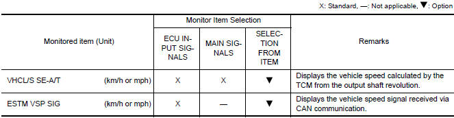
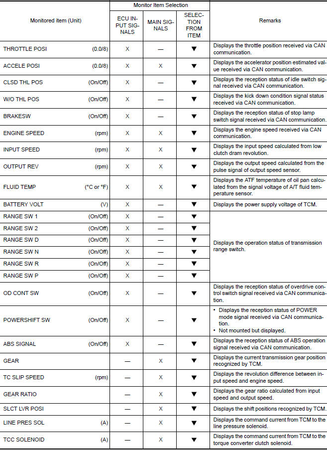
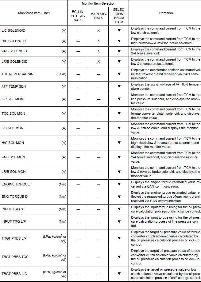
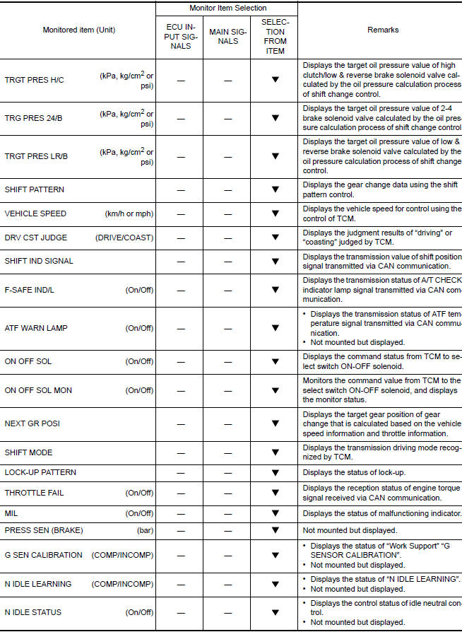
DATA MONITOR

NOTE: The following table includes information (items) inapplicable to this vehicle. For information (items) applicable to this vehicle, refer to CONSULT display items.
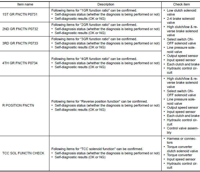
DATA MONITOR

DATA MONITOR

DATA MONITOR

DATA MONITOR

DTC WORK SUPPORT

DTC WORK SUPPORT

    More about «Transaxle & transmission (TM)»:

    Precautions

    Structure and operation

    Position switch

    Gear oil

    Side oil seal

    Position switch

    Control linkage

    Air breather hose

    5Th main gear assembly

    Transaxle assembly

    Transaxle assembly

    Input shaft and gear

    Mainshaft and gear

    Final drive

    Precautions

    A/T Control system

    A/T Shift lock system

    Transaxle

    A/T control system

    Line pressure control

    Shift change control

    Lock-up control

    Diagnosis description

    Consult function

    TCM

    Diagnosis and repair work flow

    Additional service when replacing TCM

    Additional service when replacing transaxle assembly

    A/T Fluid cooler

    Stall test

    Line pressure test

    U0073 Communication bus a off

    U0100 Lost communication (ECM A)

    U0140 Lost communication (BCM)

    U0155 Lost communication (IPC)

    U0300 Can communication data

    U1000 Can comm circuit

    U1117 Lost communication (ABS)

    P062F EEPROM

    P0705 Transmission range switch A

    P0706 Transmission range sensor A

    P0711 Transmission fluid temperature sensor A

    P0712 Transmission fluid temperature sensor A

    P0713 Transmission fluid temperature sensor A

    P0717 Input speed sensor A

    P0720 Output speed sensor

    P072C Stuck in 1GR

    P072D Stuck in 2GR

    P072E Stuck in 3GR

    P072F Stuck in 4GR

    P0731 1GR Incorrect ratio

    P0732 2GR Incorrect ratio

    P0733 3GR Incorrect ratio

    P0734 4GR Incorrect ratio

    P073E Unable to engage r range

    P073F Unable to engage 1GR

    P0740 Torque converter

    P0743 Torque converter

    P0744 Torque converter

    P074A Unable to engage 2GR

    P074B Unable to engage 3GR

    P074C Unable to engage 4GR

    P0863 TCM Communication

    P0890 TCM

    P0962 Pressure control solenoid A

    P0963 Pressure control solenoid A

    P0973 Shift solenoid A

    P0974 Shift solenoid A

    P0976 Shift solenoid B

    P0977 Shift solenoid B

    P0979 Shift solenoid C

    P0980 Shift solenoid C

    P0982 Shift solenoid D

    P0983 Shift solenoid D

    P2760 Torque converter

    Main power supply and ground circuit

    Overdrive control switch

    O/D OFF indicator lamp

    Shift position indicator circuit

    Shift lock system

    A/T Fluid

    A/T Shift selector

    Control cable

    Key interlock cable

    TCM

    Oil pan

    Output speed sensor

    Differential side oil seal

    Fluid cooler tube

    Transmission assembly

    Service data and specifications (SDS)

    Precautions

    Component parts

    Shift lock system

    Structure and operation

    Fluid cooler & fluid warmer system

    CVT Control system

    Line pressure control

    Shift control

    Lock-up control

    Idle neutral control

    Diagnosis system (TCM)

    TCM

    Diagnosis and repair work flow

    Additional service when replacing TCM

    Additional service when replacing transaxle assembly

    Calibration of G Sensor

    CVT Fluid cooler system

    Stall test

    Line pressure test

    U0073 Communication bus A off

    U0100 Lost communication (ECM A)

    U0140 Lost communication (BCM)

    U0141 Lost communication (BCM A)

    U0155 Lost communication (IPC)

    U0300 Can communication data

    U1000 Can COMM circuit

    U1117 Lost communication (ABS)

    P062F EEPROM

    P0705 Transmission range sensor A

    P0706 Transmission range sensor A

    P0711 Transmission fluid temperature sensor A

    P0712 Transmission fluid temperature sensor A

    P0713 Transmission fluid temperature sensor A

    P0715  Input speed sensor A

    P0720 Output speed sensor

    P0740 Torque converter

    P0743 Torque converter

    P0744 Torque converter

    P0746 Pressure control solenoid A

    P0846 Transmission fluid pressure SEN/SW B

    P0847 Transmission fluid pressure SEN/SW B

    P0848 Transmission fluid pressure SEN/SW B

    P0863 TCM Communication

    P0890 TCM

    P0962 Pressure control solenoid A

    P0963 Pressure control solenoid A

    P0965 Pressure control solenoid B

    P0966 Pressure control solenoid B

    P0967 Pressure control solenoid B

    P0998 Shift solenoid F

    P0999 Shift solenoid F

    P099B Shift solenoid G

    P099C Shift solenoid G

    P1586 G Sensor

    P1588 G Sensor

    P2765 Clutch B speed sensor

    P2857 Clutch A pressure

    P2858 Clutch B pressure

    P2859 Clutch A pressure

    P285A Clutch B pressure

    Main power supply and ground circuit

    Overdrive control switch

    OD OFF indicator lamp

    Shift position indicator circuit

    Shift lock system

    CVT Control system

    CVT Fluid

    CVT Shift selector

    Control cable

    Key interlock cable

    TCM

    Air breather hose

    G Sensor

    Oil pan

    Primary speed sensor

    Secondary speed sensor

    Output speed sensor

    Differential side oil seal

    Water hose

    Fluid cooler hose

    PLUG

    Transmission assembly

    Service data and specifications (SDS)

    Nissan Versa Sedan Service Manual / Transmission & driveline / Transaxle & transmission (TM) / Consult function

    Nissan Versa Sedan Service Manual

    Categories


    © 2017-2024 Copyright www.niveguide.com