
Nissan Versa (N17): Diagnosis and repair workflow
Work Flow
OVERALL SEQUENCE
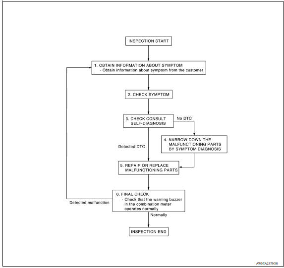
DETAILED FLOW
1.OBTAIN INFORMATION ABOUT SYMPTOM
Interview the customer to obtain as much information as possible about the conditions and environment under which the malfunction occurred.
>> GO TO 2.
2.CHECK SYMPTOM
- Check the symptom based on the information obtained from the customer.
- Check if any other malfunctions are present.
>> GO TO 3.
3.CHECK CONSULT SELF-DIAGNOSIS RESULTS
Connect CONSULT and perform self-diagnosis. Refer to MWI "CONSULT Function" (Type A) or MWI "CONSULT Function" (Type B).
Are self-diagnosis results normal?
YES >> GO TO 4.
NO >> GO TO 5.
4.NARROW DOWN MALFUNCTIONING PARTS BY SYMPTOM DIAGNOSIS
Perform symptom diagnosis and narrow down the malfunctioning parts.
>> GO TO 5.
5.REPAIR OR REPLACE MALFUNCTIONING PARTS
Repair or replace malfunctioning parts.
NOTE: If DTC is displayed, erase DTC after repairing or replacing malfunctioning parts.
>> GO TO 6.
6.FINAL CHECK
Check that the warning buzzer in the combination meter operates normally.
Does it operate normally?
YES >> Inspection End.
NO >> GO TO 1.
DTC/CIRCUIT DIAGNOSIS
 Diagnosis system (combination
meter)
Diagnosis system (combination
meter)
Other materials:
Rear suspension beam
Exploded View
1. Rear suspension beam
Removal and Installation
REMOVAL
Remove the wheel and tire assemblies using power tool. Refer to WT
"Adjustment".
Remove wheel sensor and sensor harness. Refer to BRC "REAR WHEEL SENSOR
: Removal and
Installation".
Re ...
Disc rotor
DISC ROTOR : Inspection and Adjustment
INSPECTION
Appearance
Check surface of disc rotor for uneven wear, cracks, and serious damage.
Replace it if necessary. Refer to
BR "DISC ROTOR : Inspection and Adjustment".
Runout
Fix the disc rotor to the wheel hub and bearing assembly wi ...
Categories
- Manuals Home
- Nissan Versa Owners Manual
- Nissan Versa Service Manual
- Video Guides
- Questions & Answers
- External Resources
- Latest Updates
- Most Popular
- Sitemap
- Search the site
- Privacy Policy
- Contact Us

0.0064