Nissan Versa (N17): Door request switch
Component Function Check
1.CHECK FUNCTION
- Select INTELLIGENT KEY of CM using CONSULT.
- Select REQ SW-DR, REQ SW-AS in DATA MONITOR mode.
- Check that the function operates normally according to the following
conditions.
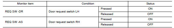
Is the inspection result normal?
YES >> Front door request switch is OK.
NO >> Refer to DLK "Diagnosis Procedure".
Diagnosis Procedure
Regarding Wiring Diagram information, refer to DLK "INTELLIGENT KEY SYSTEM : Wiring Diagram".
1.CHECK DOOR REQUEST SWITCH INPUT SIGNAL
- Turn ignition switch OFF.
- Disconnect malfunctioning front door request switch connector.
- Check voltage between malfunctioning front door request switch harness
connector and ground.
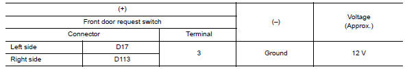
Is the inspection result normal?
YES >> GO TO 3.
NO >> GO TO 2.
2.CHECK DOOR REQUEST SWITCH CIRCUIT
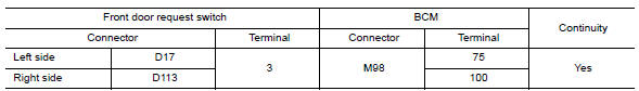
- Disconnect BCM connector.
- Check continuity between malfunctioning front door request switch
harness connector and BCM harness
connector.
- Check continuity between malfunctioning front door request switch
harness connector and ground.
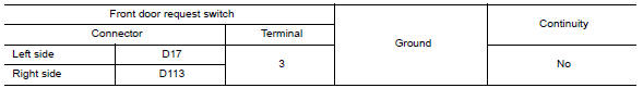
Is the inspection result normal?
YES >> Replace BCM. Refer to BCS "Removal and Installation".
NO >> Repair or replace harness.
3.CHECK DOOR REQUEST SWITCH GROUND CIRCUIT
Check continuity between malfunctioning front door request switch harness
connector and ground. 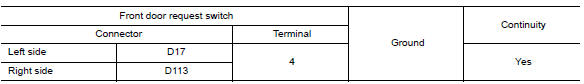
Is the inspection result normal?
YES >> GO TO 4.
NO >> Repair or replace harness.
4.CHECK DOOR REQUEST SWITCH
Refer to DLK "Component Inspection".
Is the inspection result normal?
YES >> GO TO 5.
NO >> Replace malfunctioning front door request switch.
5.CHECK INTERMITTENT INCIDENT
Refer to GI "Intermittent Incident".
>> Inspection End.
Component Inspection
1.CHECK DOOR REQUEST SWITCH
- Turn ignition switch OFF.
- Disconnect malfunctioning front door request switch connector.
- Check continuity between malfunctioning front door request switch
terminals.
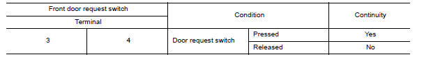
Is the inspection result normal?
YES >> Inspection End.
NO >> Replace malfunctioning front door request switch.
 Door lock and unlock switch
Other materials:
Bluetooth Hands-Free Phone System without Navigation System (Type B) (if so
equipped)
WARNING
Use a phone after stopping your vehicle
in a safe location. If you have to use a
phone while driving, exercise extreme
caution at all times so full attention may
be given to vehicle operation.
If you are unable to devote full attention
to vehicle operation while talking on
...
U0100 Lost communication (ECM A)
DTC Logic
DTC DETECTION LOGIC
DTC
Trouble diagnosis name
DTC detection condition
Possible causes
U0100
Lost Communication With
ECM/PCM "A"
When the ignition switch is ON,
TCM is unable to receive the
CAN communications signal
from ECM continuously for 2
...
Categories
- Manuals Home
- Nissan Versa Owners Manual
- Nissan Versa Service Manual
- Video Guides
- Questions & Answers
- External Resources
- Latest Updates
- Most Popular
- Sitemap
- Search the site
- Privacy Policy
- Contact Us

0.0068