Nissan Versa (N17): Front power window switch (passenger side)
Component Function Check
1. CHECK FUNCTION
Check front power window motor RH operation with front power window switch RH.
Is the inspection result normal?
YES >> Inspection End.
NO >> Refer to PWC "Diagnosis Procedure".
Diagnosis Procedure
Regarding Wiring Diagram information, refer to PWC "Wiring Diagram".
1.CHECK FRONT POWER WINDOW SWITCH RH INPUT SIGNAL
1. Turn ignition switch OFF.
2. Disconnect front power window switch RH connector.
3. Turn ignition switch ON.
4. Check voltage between front power window switch RH harness connector and
ground.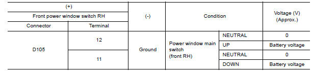
Is the inspection result normal?
YES >> GO TO 3.
NO >> GO TO 2.
2.CHECK FRONT POWER WINDOW SWITCH RH CIRCUIT
1. Turn ignition switch OFF.
2. Disconnect power window main switch connector.
3. Check continuity between power window main switch harness connector and
front power window switch
RH harness connector.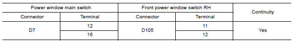
4. Check continuity between power window main switch harness connector and
ground.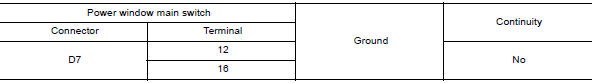
Is the inspection result normal?
YES >> Replace power window main switch. Refer to PWC "Removal and Installation".
NO >> Repair or replace harness.
3.CHECK FRONT POWER WINDOW SWITCH RH
Check front power window switch RH.
Refer to PWC "Component Inspection".
Is the inspection result normal?
YES >> Check Intermittent incident. Refer to GI "Intermittent Incident".
NO >> Replace front power window switch RH. Refer to PWC "Removal and Installation".
Component Inspection
1.CHECK FRONT POWER WINDOW SWITCH RH
1. Turn ignition switch OFF.
2. Disconnect front power window switch RH connector.
3. Check front power window switch RH terminals under the following
conditions.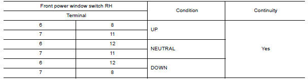
Is the inspection result normal?
YES >> Inspection End.
NO >> Replace front power window switch RH. Refer to PWC "Removal and Installation".
 Power supply and ground circuit
Rear power window switch
Component Function Check 1. CHECK FUNCTION Check rear power window motor operation with rear power window switch. Is the inspection result normal? YES >> Inspection End. NO >> Refer ...
Other materials:
Precautions
Precaution for Supplemental Restraint System
(SRS) "AIR BAG" and "SEAT BELT PRE-TENSIONER"
The Supplemental Restraint System such as "AIR BAG" and "SEAT BELT PRE-TENSIONER",
used along
with a front seat belt, helps to reduce the risk or severity of injury to the
driver and ...
Trunk lid opener cable
TRUNK LID OPENER CABLE : Removal and Installation
REMOVAL
1. Remove trunk lid striker. Refer to DLK "TRUNK LID STRIKER : Removal and
Installation".
2. Remove trunk side finisher (LH). Refer to INT "TRUNK SIDE FINISHER :
Removal and Installation".
3. Remove rear seat cushi ...
Categories
- Manuals Home
- Nissan Versa Owners Manual
- Nissan Versa Service Manual
- Video Guides
- Questions & Answers
- External Resources
- Latest Updates
- Most Popular
- Sitemap
- Search the site
- Privacy Policy
- Contact Us

0.0075