Nissan Versa (N17): P0182, P0183 FTT sensor
DTC Logic
DTC DETECTION LOGIC
| DTC No. | Trouble diagnosis name | DTC detecting condition | Possible cause |
| P0182 | FTT SEN/CIRCUIT (Fuel tank temperature sensor circuit low input) | An excessively low voltage from the sensor is sent to ECM. |
|
| P0183 | FTT SEN/CIRCUIT (Fuel tank temperature sensor circuit high input) | An excessively high voltage from the sensor is sent to ECM. |
DTC CONFIRMATION PROCEDURE
1.PRECONDITIONING
If DTC Confirmation Procedure has been previously conducted, always perform the following procedure before conducting the next test.
- Turn ignition switch OFF and wait at least 10 seconds.
- Turn ignition switch ON.
- Turn ignition switch OFF and wait at least 10 seconds.
>> GO TO 2.
2.PERFORM DTC CONFIRMATION PROCEDURE
- Turn ignition switch ON and wait at least 5 seconds.
- Check 1st trip DTC.
Is 1st trip DTC detected?
YES >> Proceed to EC, "Diagnosis Procedure".
NO >> INSPECTION END
Diagnosis Procedure
1.CHECK DTC WITH COMBINATION METER
Check DTC with combination meter. Refer to MWI, "CONSULT Function" (TYPE A) or MWI, "CONSULT Function" (TYPE B). Check the vehicle type to confirm the service information in MWI section. Refer to MWI, "Information".
Is the inspection result normal?
YES >> GO TO 2.
NO >> Proceed to MWI, "Component Function Check" (TYPE A) or MWI, "Component Function Check" (TYPE B).
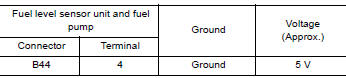
2.CHECK FUEL TANK TEMPERATURE (FTT) SENSOR POWER SUPPLY
- Turn ignition switch OFF.
- Disconnect fuel level sensor unit and fuel pump harness connector.
- Turn ignition switch ON.
- Check the voltage between fuel level sensor unit and fuel pump harness
connector and ground.
Is the inspection result normal?
YES >> GO TO 4.
NO >> GO TO 3.
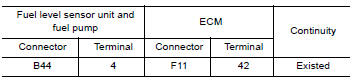
3.CHECK FUEL TANK TEMPERATURE (FTT) SENSOR POWER SUPPLY CIRCUIT
- Turn ignition switch OFF.
- Disconnect ECM harness connector.
- Check the continuity between fuel level sensor unit and fuel pump
harness connector and ECM harness
connector.
4. Also check harness for short to ground and to power.
Is the inspection result normal?
YES >> Perform the trouble diagnosis for power supply circuit.
NO >> Repair or replace errordetected parts.
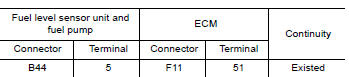
4.CHECK FUEL TANK TEMPERATURE (FTT) SENSOR GROUND CIRCUIT
- Turn ignition switch OFF.
- Disconnect ECM harness connector.
- Check the continuity between fuel level sensor unit and fuel pump
harness connector and ECM harness
connector.
4. Also check harness for short to power.
Is the inspection result normal?
YES >> GO TO 5.
NO >> Repair or replace errordetected parts.
5.CHECK FUEL TANK TEMPERATURE (FTT) SENSOR
Check the FTT sensor. Refer to EC, "Component Inspection".
Is the inspection result normal?
YES >> Check intermittent incident. Refer to GI, "Intermittent Incident".
NO >> Replace "fuel level sensor unit and fuel pump". Refer to FL, "Removal and Installation".
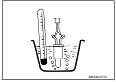
Component Inspection
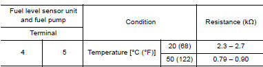
1.CHECK FUEL TANK TEMPERATURE (FTT) SENSOR
- Turn ignition switch OFF.
- Disconnect fuel level sensor unit and fuel pump harness connector.
- Remove fuel level sensor unit. Refer to FL5, "Removal and Installation".
- Check resistance between fuel level sensor unit and fuel pump
terminals by heating with hot water as shown in the figure.
Is the inspection result normal?
YES >> INSPECTION END
NO >> Replace fuel level sensor unit and fuel pump. Refer to FL, "Removal and Installation".
 P0181 FTT sensor
Other materials:
P0734 4GR Incorrect ratio
Description
This malfunction is detected when the A/T does not shift into 4GR position as
instructed by TCM. This is not
only caused by electrical malfunction (circuits open or shorted) but by
mechanical malfunction such as control
valve sticking, improper solenoid valve operation, etc.
DTC ...
P2760 Torque converter
Description
This DTC is detected when the torque converter clutch solenoid valve is
electrically normal but the torque converter
clutch does not engage. This is not due to an electrical malfunction (circuit
open or shorted), but is
instead due to a mechanical malfunction (sticking of the con ...
Categories
- Manuals Home
- Nissan Versa Owners Manual
- Nissan Versa Service Manual
- Video Guides
- Questions & Answers
- External Resources
- Latest Updates
- Most Popular
- Sitemap
- Search the site
- Privacy Policy
- Contact Us

0.007