Nissan Versa (N17): Diagnosis system (IPDM E/R)
Diagnosis Description
AUTO ACTIVE TEST
Description
In auto active test, the IPDM E/R sends a drive signal to the following systems to check their operation.
- Front wiper (LO, HI)
- Parking lamp
- License plate lamp
- Tail lamp
- Front fog lamp
- Headlamp (LO, HI)
- A/C compressor (magnet clutch)
- Cooling fan
Operation Procedure
NOTE: Never perform auto active test in the following conditions.
- Passenger door is open
- CONSULT is connected
1. Close the hood and lift the wiper arms from the windshield. (Prevent windshield damage due to wiper operation) NOTE: When auto active test is performed with hood opened, sprinkle water on windshield beforehand.
2. Turn the ignition switch OFF.
3. Turn the ignition switch ON, and within 20 seconds, press the driver door switch 10 times. Then turn the ignition switch OFF.
4. Turn the ignition switch ON within 10 seconds. After that the horn sounds once and the auto active test starts.
5. After a series of the following operations is repeated 3 times, auto active test is completed.
NOTE:
- When auto active test has to be cancelled halfway through test, turn the ignition switch OFF.
- When auto active test is not activated, door switch may be the cause. Check door switch. Refer to DLK "Component Function Check".
Inspection in Auto Active Test
When auto active test is actuated, the following operation sequence is
repeated 3 times.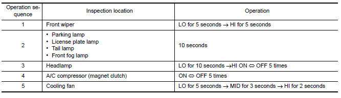
Concept of Auto Active Test
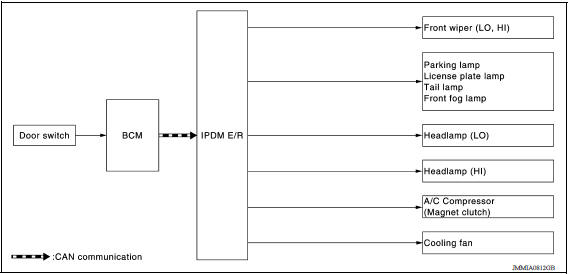
- IPDM E/R starts the auto active test with the door switch signals
transmitted by BCM via CAN communication.
Therefore, the CAN communication line between IPDM E/R and BCM is considered normal if the auto active test starts successfully.
- The auto active test facilitates troubleshooting if any systems controlled by IPDM E/R cannot be operated.
Diagnosis Chart in Auto Active Test 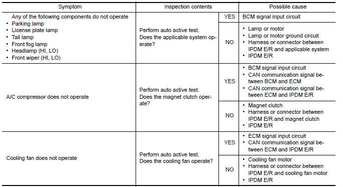
Consult Function (IPDM E/R)
APPLICATION ITEM
CONSULT performs the following functions via CAN communication with IPDM E/R. 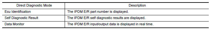

ECU IDENTIFICATION
The IPDM E/R part number is displayed.
SELF DIAGNOSTIC RESULT Refer to PCS "DTC Index".
DATA MONITOR 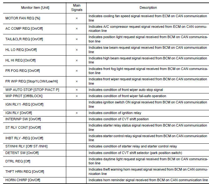
ACTIVE TEST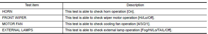
CAN DIAG SUPPORT MNTR
Refer to LAN "CAN Diagnostic Support Monitor".
ECU DIAGNOSIS INFORMATION
ECM, IPDM E/R, BCM
List of ECU Reference
| ECU | Reference |
| ECM | EC "Reference Value" |
| EC "Wiring Diagram" | |
| EC "Fail Safe" | |
| EC "DTC Inspection Priority Chart" | |
| EC "DTC Index" | |
| IPDM E/R | PCS "Reference Value" |
| PCS "Wiring Diagram" | |
| PCS"Fail-Safe" | |
| PCS"DTC Index" | |
| BCM | BCS "Reference Value" |
| BCS "Wiring Diagram" | |
| BCS "Fail-safe" | |
| BCS "DTC Inspection Priority Chart" | |
| BCS "DTC Index" |
WIRING DIAGRAM
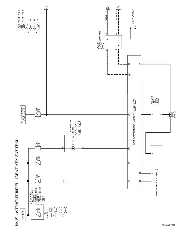
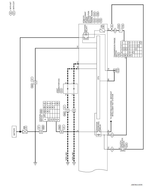
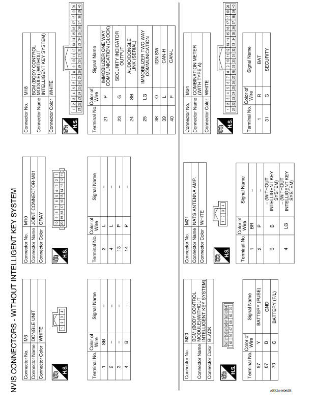
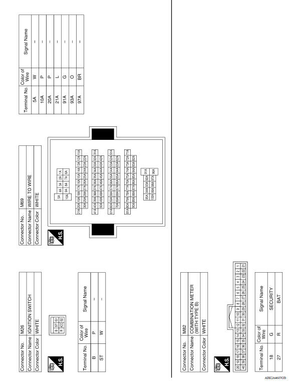
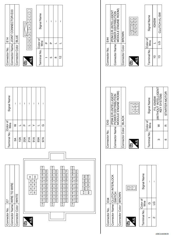
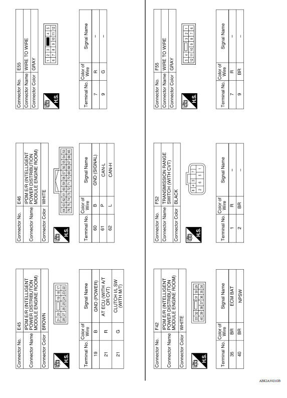
NVIS
Wiring Diagram
BASIC INSPECTION
 Nissan vehicle immobilizer system-NATS
NISSAN VEHICLE IMMOBILIZER SYSTEMNATS : System Diagram NISSAN VEHICLE IMMOBILIZER SYSTEMNATS : System Description INPUT/OUTPUT SIGNAL CHART BCM &n ...
Diagnosis and repair workflow
Work Flow OVERALL SEQUENCE DETAILED FLOW 1.GET INFORMATION FOR SYMPTOM Get the detailed information from the customer about the symptom (the condition and the environment when the incident/ ...
Other materials:
Rear oil seal
REAR OIL SEAL : Removal and Installation
REMOVAL
Remove transaxle assembly.
Remove clutch cover and clutch disk (M/T models).
Remove flywheel (M/T models) or drive plate (A/T or CVT models).
Remove rear oil seal with a suitable tool.
CAUTION:
Be careful not to damage crankshaft an ...
Component parts
Component Parts Location
1. Condenser 2. Compressor 3. Refrigerant pressure sensor
4. Liquid tank 5. Evaporator 6. Expansion valve
A. Built-in heater & cooling unit assembly
Component Description
Component
Description
Evaporator
The mist form liquid refrigerant t ...
Categories
- Manuals Home
- Nissan Versa Owners Manual
- Nissan Versa Service Manual
- Video Guides
- Questions & Answers
- External Resources
- Latest Updates
- Most Popular
- Sitemap
- Search the site
- Privacy Policy
- Contact Us

0.0054