Nissan Versa (N17): DLC Branch line circuit
Diagnosis Procedure
1.CHECK CONNECTOR
1. Turn the ignition switch OFF.
2. Disconnect the battery cable from the negative terminal.
3. Check the terminals and connectors of the data link connector for damage, bend and loose connection (connector side and harness side).
Is the inspection result normal?
YES >> GO TO 2.
NO >> Repair the terminal and connector.
2.CHECK HARNESS FOR OPEN CIRCUIT
Check the resistance between the data link connector terminals.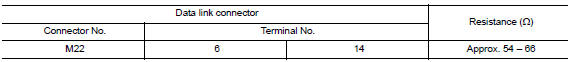
Is the measurement value within the specification?
YES (Present error)>>Check CAN system type decision again.
YES (Past error)>>Error was detected in the data link connector branch line circuit.
NO >> Repair the data link connector branch line.
 AV Branch line circuit
Diagnosis Procedure 1.CHECK CONNECTOR 1. Turn the ignition switch OFF. 2. Disconnect the battery cable from the negative terminal. 3. Check the terminals and connectors of the AV control unit for ...
EPS Branch line circuit
Diagnosis Procedure 1.CHECK CONNECTOR 1. Turn the ignition switch OFF. 2. Disconnect the battery cable from the negative terminal. 3. Check the terminals and connectors of the EPS control unit f ...
Other materials:
Accelerator pedal released position
learning
Description
Accelerator Pedal Released Position Learning is a function of ECM to learn
the fully released position of the
accelerator pedal by monitoring the accelerator pedal position sensor output
signal. It must be performed each
time harness connector of accelerator pedal position senso ...
Clutch pedal
Inspection and Adjustment
1. Check to see if the master cylinder rod end moves freely.
It
should not be bound by the clutch pedal.
a. If the rod end does not move freely, remove the rod end and
check for deformation or damage on the rod end. Leave the rod
end removed ...
Categories
- Manuals Home
- Nissan Versa Owners Manual
- Nissan Versa Service Manual
- Video Guides
- Questions & Answers
- External Resources
- Latest Updates
- Most Popular
- Sitemap
- Search the site
- Privacy Policy
- Contact Us

0.0052