Nissan Versa (N17): Drive belt
DRIVE BELT : Exploded View
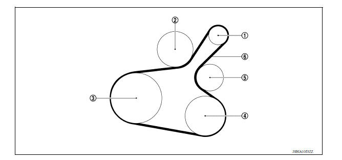
1. Generator 2. Water pump 3. Crankshaft pulley 4. A/C compressor (with A/C models) Idler pulley (without A/C models) 5. Idler pulley 6. Drive belt
DRIVE BELT : Inspection
- Inspection should be done only when engine is cold or over 30 minutes after the engine is stopped.
(1) : Generator
(2) : Water pump
(3) : Crankshaft pulley
(4) : A/C compressor (with A/C models) : Idler pulley (without A/C models)
(5) : Idler pulley
(6) : Drive belt
- Visually check belt for wear, damage, and cracks on inside and edges.
- Turn crankshaft pulley clockwise twice, and check that the tension on all pulleys equalizes before testing.
- When measuring deflection, apply 98.1 N (10 kg, 22 lb) at the (
 ) marked point.
 - Measure the belt tension and frequency with acoustic tension gauge at
the (
 ) marked point.
CAUTION:
- When the tension and frequency are measured, the acoustic tension gauge should be used.
- When checking immediately after installation, first adjust it to the specified value. Then, after turning crankshaft two turns or more, readjust to the specified value to avoid variation in deflection between pulleys.
Belt deflection/belt tension and frequency : Refer to EM "Drive Belt".
DRIVE BELT : Adjustment 
CAUTION:
- When belt is replaced with new one, adjust belt tension to the value for "New belt," because new belt will not fully seat in the pulley groove.
- When tension of the belt being used exceeds "Limit," adjust it to the value for "After adjusted."
- When installing a belt, check it is correctly engaged with the pulley groove.
- Do not allow oil or engine coolant to get on the belt.
- Do not twist or bend the belt strongly.
1. Remove the fender protector (RH) front side clip. Refer to EXT "Removal and Installation".
2. Tighten lock nut (A) temporarily to the following torque.
Lock nut (A) (Temporary tightening) : 4.4 N*m (0.45 kg-m, 39 in-lb)
(1) : Generator
(2) : Water pump
(3) : Crankshaft pulley
(4) : A/C compressor (with A/C models) : Idler pulley (without A/C models)
(5) : Idler pulley
(6) : Drive belt
(B) : Adjusting bolt
3. Adjust the belt tension by turning the adjusting bolt. Refer to EM "Drive Belt".
CAUTION:
- When checking immediately after installation, first adjust it to the specified value. Then, after turning crankshaft two turns or more, readjust to the specified value to avoid variation in deflection between pulleys.
- When the tension adjustment is performed, the lock nut should be in the condition at Step 2. If the tension adjustment is performed when the lock nut is loosened more than the temporary tightening, the idler pulley tilts and the correct tension adjustment cannot be performed.
4. Tighten the lock nut to final tightening specification.
Lock nut (Final tightening) : 34.8 N*m (3.5 kg-m, 26 ft-lb)
 Chassis and body maintenance
Engine coolant
ENGINE COOLANT : Inspection CHECKING COOLING SYSTEM HOSES Check hoses for the following: Improper attachment Leaks Cracks Damage Loose connections Chafing Deterioration CHECKING R ...
Other materials:
Air conditioning cut control
AIR CONDITIONING CUT CONTROL : System Diagram
AIR CONDITIONING CUT CONTROL : System
Description
INPUT/OUTPUT SIGNAL CHART
Sensor
Input signal to ECM
ECM function
Actuator
Crankshaft position sensor (POS)
Camshaft position sensor (PHASE)
Engine speed*1
Pisto ...
Low-pressure flexible hose
Removal and Installation
CAUTION:
Perform oil return operation before each refrigeration system disassembly.
However, if a large amount
of refrigerant or oil is detected, do not perform oil return operation. Refer to
HA "Perform Oil
Return Operation".
REMOVAL
Use refrigerant ...
Categories
- Manuals Home
- Nissan Versa Owners Manual
- Nissan Versa Service Manual
- Video Guides
- Questions & Answers
- External Resources
- Latest Updates
- Most Popular
- Sitemap
- Search the site
- Privacy Policy
- Contact Us

0.005