Nissan Versa (N17): Drive belt idler pulley
Exploded View
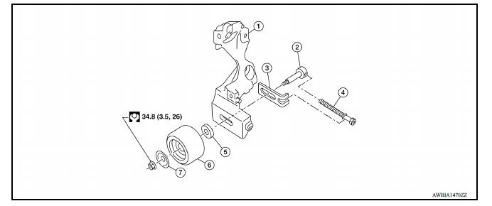
1. Generator bracket 2. Center shaft 3. Spacer 4. Adjusting bolt 5. Washer 6. Idler pulley 7. Plate
Removal and Installation
REMOVAL
- Remove the fender protector (RH).
- Remove the air duct inlet assembly.
- Remove drive belt.
- Remove the lock nut, and then remove the plate, idler pulley, and washer.
- Remove the center shaft together with the spacer and the adjusting bolt.
INSTALLATION
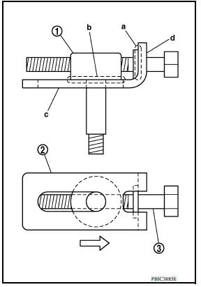
- Insert the center shaft (1) into the slide groove of the spacer (2).Fully screw in the adjusting bolt (3) in the belt loosening direction
(
 ).
).
- At that time, place the flange (a) of the adjusting bolt and the seat (b) of the center shaft on the spacer.
- Place each surface (c and d) of the spacer on the generator bracket. Install the washer, idler pulley, and plate, and then temporarily tighten the lock nut.
Lock nut (Temporary tightening) : 4.4 N*m (0.45 kgm, 39 inlb)
- Installation is in the reverse order of removal.
 Spark plug
Exploded View 1. Ignition coil 2. Spark plug Removal and Installation REMOVAL 1. Remove ignition coil. CAUTION: Do not drop or shock ignition coil. 2. Remove spark plug using a suitable tool. ...
Air cleaner and air duct
Exploded View 1. Clamp 2. PCV hose 3. Clamp 4. Mount rubber 5. Air duct (inlet) 6. Air cleaner body 7. Grommet 8. Air cleaner filter 9. Air cleaner cover 10. Mass air flow sensor 11. Air duct ...
Other materials:
Vehicle Dynamic Control (VDC) system (if so equipped)
The VDC system uses various sensors to monitor
driver inputs and vehicle motion. Under certain
driving conditions, the VDC System helps to perform
the following functions:
Controls brake pressure to reduce wheel
slip on one slipping drive wheel so power is
transferred to a non slipping drive w ...
P0982 Shift solenoid D
DTC Logic
DTC DETECTION LOGIC
DTC
Trouble diagnosis name
DTC detection condition
Possible causes
P0982
Shift Solenoid D Control Circuit
Low
The following diagnosis conditions
are met, and the current
monitor reading of the TCM
high clutch/low & revers ...
Categories
- Manuals Home
- Nissan Versa Owners Manual
- Nissan Versa Service Manual
- Video Guides
- Questions & Answers
- External Resources
- Latest Updates
- Most Popular
- Sitemap
- Search the site
- Privacy Policy
- Contact Us

0.0049