Nissan Versa (N17): C1105, C1106, C1107, C1108 Wheel sensor
DTC Logic
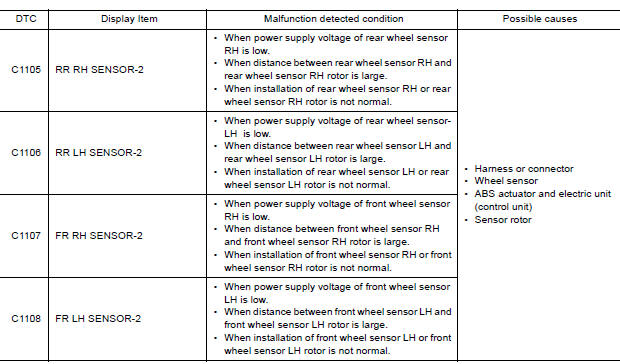
DTC DETECTION LOGIC
DTC CONFIRMATION PROCEDURE
1.CHECK SELF DIAGNOSTIC RESULT
With CONSULT.
- Start engine and drive vehicle at approximately 30 km/h (19 MPH) or more for approximately 1 minute.
- Perform self diagnostic result.
Is DTC C1105, C1106, C1107 or C1108 detected?
YES >> Proceed to diagnosis procedure. Refer to BRC "Diagnosis Procedure".
NO >> Inspection End.
Diagnosis Procedure
Regarding Wiring Diagram information, refer to BRC "Wiring Diagram".
CAUTION: Do not check between wheel sensor terminals.
1.CONNECTOR INSPECTION
- Disconnect ABS actuator and electric unit (control unit) connector E33 and wheel sensor connector of wheel with DTC.
- Check terminals for deformation, disconnection, looseness or damage.
Is the inspection result normal?
YES >> GO TO 2
NO >> Repair or replace as necessary.
2.CHECK WHEEL SENSOR OUTPUT SIGNAL
- Connect ABS active wheel sensor tester (J-45741) to wheel sensor using appropriate adapter.
- Turn on the ABS active wheel sensor tester power switch.
NOTE: The green POWER indicator should illuminate. If the POWER indicator does not illuminate, replace the battery in the ABS active wheel sensor tester before proceeding.
- Spin the wheel of the vehicle by hand and observe the red SENSOR
indicator on the ABS active wheel
sensor tester. The red SENSOR indicator should flash on and off to indicate
an output signal.
NOTE: If the red SENSOR indicator illuminates but does not flash, reverse the polarity of the tester leads and retest.
Does the ABS active wheel sensor tester detect a signal?
YES >> GO TO 3
NO >> Replace the wheel sensor. Refer to BRC "FRONT WHEEL SENSOR : Removal and Installation" (front) or BRC, "REAR WHEEL SENSOR : Removal and Installation" (rear).
3.CHECK WHEEL BEARINGS
Check wheel bearing axial end play. Refer to FAX "Inspection" (front) or RAX "Inspection" (rear).
Is the inspection result normal?
YES >> GO TO 4
NO >> Repair or replace as necessary. Refer to FAX "Removal and Installation" (front) or RAX "Removal and Installation" (rear).
4.CHECK WIRING HARNESS FOR SHORT CIRCUIT
Check continuity between wheel sensor connector terminals and ground of wheel
with DTC. 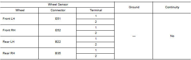
Is the inspection result normal?
YES >> Replace the ABS actuator and electric unit (control unit). Refer to BRC "Removal and Installation".
NO >> Repair the circuit.
 C1101, C1102, C1103, C1104 Wheel sensor
Other materials:
IDLE SPEED
Inspection
1.CHECK IDLE SPEED
With CONSULT
Check idle speed in "DATA MONITOR" mode with CONSULT.
Without CONSULT
Check idle speed by installing the pulse type tachometer clamp on the loop
wire or on suitable high-tension
wire which installed between No.1 ignition coil and No.1 spark plug.
...
Wheel alignment
Inspection
DESCRIPTION
CAUTION:
The adjustment mechanisms of camber and toe-in are not included.
If camber and toe-in is outside the standard, check front
suspension parts for wear and damage.
Replace suspect parts if a malfunction is detected.
Measure wheel alignment under unladen ...
Categories
- Manuals Home
- Nissan Versa Owners Manual
- Nissan Versa Service Manual
- Video Guides
- Questions & Answers
- External Resources
- Latest Updates
- Most Popular
- Sitemap
- Search the site
- Privacy Policy
- Contact Us

0.0057