Nissan Versa (N17): B2195 Anti-scanning
DTC Logic
DTC DETECTION LOGIC 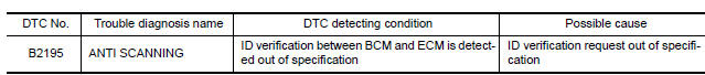
1.PERFORM DTC CONFIRMATION PROCEDURE
1. Turn ignition switch ON.
2. Check DTC in "Self Diagnostic Result" mode of "BCM" using CONSULT.
Is DTC detected?
YES >> Refer to SEC "Diagnosis Procedure".
NO >> Inspection End.
Diagnosis Procedure
1.CHECK SELF DIAGNOSTIC RESULT 1
1. Select "Self Diagnostic Result" of "BCM" using CONSULT.
2. Erase DTC.
3. Perform DTC Confirmation Procedure for DTC P2195. Refer to SEC "DTC Logic".
Is DTC detected?
YES >> GO TO 2.
NO >> Inspection End.
2.CHECK EQUIPMENT OF THE VEHICLE
Check that unspecified accessory part related to engine start is not installed.
Is unspecified accessory part related to engine start installed?
YES >> GO TO 3.
NO >> GO TO 4.
3.CHECK SELF DIAGNOSTIC RESULT 2
1. Obtain the customer's approval to remove unspecified accessory part related to engine start, and then remove it.
2. Select "Self Diagnostic Result" of "BCM" using CONSULT.
3. Erase DTC.
4. Perform DTC CONFIRMATION PROCEDURE for DTC B2195. Refer to SEC "DTC Logic".
Is DTC detected?
YES >> GO TO 4.
NO >> Inspection End.
4.REPLACE BCM
1. Replace BCM. Refer to BCS "Removal and Installation".
2. Perform initialization of BCM and registration of all ignition keys using CONSULT.
For initialization and registration procedures, refer to CONSULT Immobilizer mode and follow the onscreen instructions.
>> Inspection End.
 B2193, P1612 Chain of ECM-IMMU
Description BCM performs the ID verification with ECM that allows the engine to start. BCM starts the communication with ECM if ignition switch is turned ON and starts the engine if the ID is OK. ...
B2196 Dongle unit
Description BCM performs ID verification between BCM and dongle unit. When verification result is OK, BCM permits cranking. ...
Other materials:
Recommended fluids/lubricants and capacities
The following are approximate capacities. The actual refill capacities may
be a little different. When refilling, follow the procedure
described in the "Do-it-yourself" section to determine the proper refill
capacity.
...
Spark plug
Exploded View
1. Ignition coil 2. Spark plug
Removal and Installation
REMOVAL
1. Remove ignition coil.
CAUTION:
Do not drop or shock ignition coil.
2. Remove spark plug using a suitable tool.
Diameter (a) : 14 mm (0.55 in)
CAUTION:
Do not drop or shock spark plug.
INSPECTION AFTER REM ...
Categories
- Manuals Home
- Nissan Versa Owners Manual
- Nissan Versa Service Manual
- Video Guides
- Questions & Answers
- External Resources
- Latest Updates
- Most Popular
- Sitemap
- Search the site
- Privacy Policy
- Contact Us

0.0052