Nissan Versa (N17): P1572 ASCD brake switch
DTC Logic
DTC DETECTION LOGIC
NOTE:
- If DTC P1572 is displayed with DTC P0605, first perform the trouble diagnosis for DTC P0605. Refer to EC, "DTC Logic".
- This self-diagnosis has the one trip detection logic. When
malfunction A is detected, DTC is not
stored in ECM memory. And in that case, 1st trip DTC and 1st trip freeze
frame data are displayed.
1st trip DTC is erased when ignition switch OFF. And even when malfunction A is detected in two consecutive trips, DTC is not stored in ECM memory.
| DTC No. | Trouble diagnosis (Trouble diagnosis content) | DTC detecting condition | Possible cause | |
| P1572 | ASCD BRAKE SW (Brake pedal position switch) | A | When the vehicle speed is above 30 km/h (19 MPH), ON signals from the stop lamp switch and the brake pedal position switch are sent to the ECM at the same time. |
|
| B | Brake pedal position switch signal is not sent to ECM for extremely long time while the vehicle is driving. | |||
DTC CONFIRMATION PROCEDURE
1.PRECONDITIONING
If DTC Confirmation Procedure has been previously conducted, always perform the following procedure before conducting the next test.
- Turn ignition switch OFF and wait at least 10 seconds.
- Turn ignition switch ON.
- Turn ignition switch OFF and wait at least 10 seconds.
NOTE: Procedure for malfunction B is not described here. It takes extremely long time to complete procedure for malfunction B. By performing procedure for malfunction A, the incident that causes malfunction B can be detected.
>> GO TO 2.
2.PERFORM DTC CONFIRMATION PROCEDURE FOR MALFUNCTION A
- Start engine.
- Press MAIN switch and make sure that CRUISE indicator is displayed in combination meter.
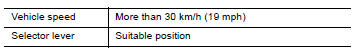
- Drive the vehicle for at least 5 consecutive seconds as per the following conditions.
CAUTION: Always drive vehicle at a safe speed.
NOTE: This procedure may be conducted with the drive wheels lifted in the shop or by driving the vehicle.
If a road test is expected to be easier, it is unnecessary to lift the vehicle.
4. Check DTC.
Is DTC detected?
YES >> Proceed to EC, "Diagnosis Procedure".
NO >> GO TO 3.
3.PERFORM DTC CONFIRMATION PROCEDURE FOR MALFUNCTION B
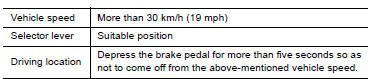
- Drive the vehicle for at least 5 consecutive seconds as per the following conditions.
CAUTION: Always drive vehicle at a safe speed.
NOTE: This procedure may be conducted with the drive wheels lifted in the shop or by driving the vehicle.
If a road test is expected to be easier, it is unnecessary to lift the vehicle.
2. Check DTC.
Is DTC detected?
YES >> Proceed to EC, "Diagnosis Procedure".
NO >> INSPECTION END
Diagnosis Procedure
1.CHECK OVERALL FUNCTION-I
With CONSULT
- Turn ignition switch ON.
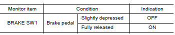
- Select "BRAKE SW1" in "DATA MONITOR" mode of "ENGINE" using CONSULT.
- Check "BRAKE SW1" indication as per the following conditions.
Without CONSULT
- Turn ignition switch ON.
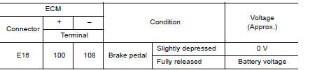
- Check the voltage between ECM harness connector terminals as per the
following.
Is the inspection result normal?
YES >> GO TO 2.
NO >> GO TO 3.
2.CHECK OVERALL FUNCTION-II
With CONSULT
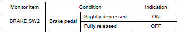
Select "BRAKE SW2" and check indication as per the following conditions.
Without CONSULT
Check the voltage between ECM harness connector terminals as per the
following conditions. 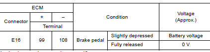
Is the inspection result normal?
YES >> Check intermittent incident. Refer to GI, "Intermittent Incident".
NO >> GO TO 6.
3.CHECK BRAKE PEDAL POSITION SWITCH POWER SUPPLY
- Turn ignition switch OFF.
- Disconnect brake pedal position switch harness connector.
- Turn ignition switch ON.
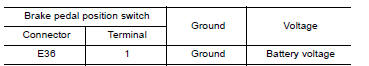
- Check the voltage between brake pedal position switch harness connector
and ground.
Is the inspection result normal?
YES >> GO TO 4.
NO >> Perform the trouble diagnosis for power supply circuit.
4.CHECK BRAKE PEDAL POSITION SWITCH INPUT SIGNAL CIRCUIT
- Turn ignition switch OFF.
- Disconnect ECM harness connector.
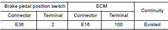
- Check the continuity between brake pedal position switch harness
connector and ECM harness connector.
- Also check harness for short to ground and to power.
Is the inspection result normal?
YES >> GO TO 5.
NO >> Repair or replace error-detected parts.
5.CHECK BRAKE PEDAL POSITION SWITCH
Check the brake pedal position switch. Refer to EC, "Component Inspection (Brake Pedal Position Switch)"
Is the inspection result normal?
YES >> Check intermittent incident. Refer to GI, "Intermittent Incident".
NO >> Replace brake pedal position switch. Refer to BR, "Exploded View".
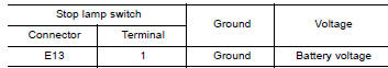
6.CHECK STOP LAMP SWITCH POWER SUPPLY CIRCUIT
- Turn ignition switch OFF.
- Disconnect stop lamp switch harness connector.
- Check the voltage between stop lamp switch harness connector and ground.
Is the inspection result normal?
YES >> GO TO 7.
NO >> Perform the trouble diagnosis for power supply circuit.
7.CHECK STOP LAMP SWITCH INPUT SIGNAL CIRCUIT
- Disconnect ECM harness connector.
- Check the continuity between stop lamp switch harness connector and ECM
harness connector.
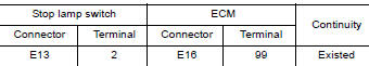
- Also check harness for short to ground and to power.
Is the inspection result normal?
YES >> GO TO 8.
NO >> Repair or replace error-detected parts.
8.CHECK STOP LAMP SWITCH
Check the stop lamp switch. Refer to EC, "Component Inspection (Stop Lamp Switch)".
Is the inspection result normal?
YES >> Check intermittent incident. Refer to GI, "Intermittent Incident".
NO >> Replace stop lamp switch. Refer to BR, "Exploded View".
Component Inspection (Brake Pedal Position Switch)
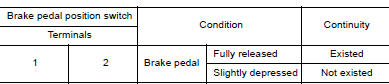
1.CHECK BRAKE PEDAL POSITION SWITCH-I
- Turn ignition switch OFF.
- Disconnect brake pedal position switch harness connector.
- Check the continuity between brake pedal position switch terminals as
per the following conditions.
Is the inspection result normal?
YES >> INSPECTION END
NO >> GO TO 2.
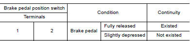
2.CHECK BRAKE PEDAL POSITION SWITCH-II
- Adjust brake pedal position switch installation. Refer to BR, "Inspection and Adjustment".
- Check the continuity between brake pedal position switch terminals as
per the following conditions.
Is the inspection result normal?
YES >> INSPECTION END
NO >> Replace brake pedal position switch. Refer to BR, "Exploded View".
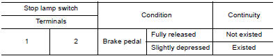
Component Inspection (Stop Lamp Switch)
1.CHECK STOP LAMP SWITCH-I
- Turn ignition switch OFF.
- Disconnect stop lamp switch harness connector.
- Check the continuity between stop lamp switch terminals as per the
following conditions.
Is the inspection result normal?
YES >> INSPECTION END
NO >> GO TO 2.
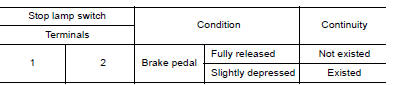
2.CHECK STOP LAMP SWITCH-II
- Adjust stop lamp switch installation. Refer to BR, "Inspection and Adjustment".
- Check the continuity between stop lamp switch terminals as per the
following conditions.
Is the inspection result normal?
YES >> INSPECTION END
NO >> Replace stop lamp switch. Refer to BR, "Exploded View".
 P1564 ASCD steering switch
P1574 ASCD vehicle speed sensor
Description The ECM receives two vehicle speed sensor signals via CAN communication line. One is sent from combination meter, and the other is from TCM (Transmission control module). The ECM use ...
Other materials:
Idle air volume learning
Description
Idle Air Volume Learning is a function of ECM to learn the idle air volume
that keeps each engine idle speed
within the specific range. It must be performed under any of the following
conditions:
Each time electric throttle control actuator or ECM is replaced.
Idle speed or ...
Ignition timing
Inspection
1.CHECK IGNITION TIMING
1. Attach timing light (A) to loop wire (1) as
shown.
2. Check ignition timing.
1 : Timing indicator
>> INSPECTION END
...
Categories
- Manuals Home
- Nissan Versa Owners Manual
- Nissan Versa Service Manual
- Video Guides
- Questions & Answers
- External Resources
- Latest Updates
- Most Popular
- Sitemap
- Search the site
- Privacy Policy
- Contact Us

0.0057