Nissan Versa (N17): ECM Branch line circuit
Diagnosis Procedure
1.CHECK CONNECTOR
1. Turn the ignition switch OFF.
2. Disconnect the battery cable from the negative terminal.
3. Check the terminals and connectors of the ECM for damage, bend and loose connection (unit side and connector side).
Is the inspection result normal?
YES >> GO TO 2.
NO >> Repair the terminal and connector.
2.CHECK HARNESS FOR OPEN CIRCUIT
1. Disconnect the connector of ECM.
2. Check the resistance between the ECM harness connector terminals.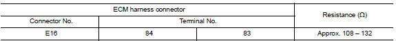
Is the measurement value within the specification?
YES >> GO TO 3.
NO >> Repair the ECM branch line.
3.CHECK POWER SUPPLY AND GROUND CIRCUIT
Check the power supply and the ground circuit of the ECM. Refer to EC "Diagnosis Procedure".
Is the inspection result normal?
YES (Present error)>>Replace the ECM. Refer to EC"Removal and Installation".
YES (Past error)>>Error was detected in the ECM branch line.
NO >> Repair the power supply and the ground circuit.
 Main line between IPDM-E and DLC
circuit
Main line between IPDM-E and DLC
circuit
Diagnosis Procedure 1.CHECK CONNECTOR 1. Turn the ignition switch OFF. 2. Disconnect the battery cable from the negative terminal. 3. Check the following terminals and connectors for damage, ben ...
ABS Branch line circuit 
Diagnosis Procedure 1.CHECK CONNECTOR 1. Turn the ignition switch OFF. 2. Disconnect the battery cable from the negative terminal. 3. Check the terminals and connectors of the ABS actuator and ele ...
Other materials:
Car phone or CB radio
When installing a CB, ham radio or car phone in
your vehicle, be sure to observe the following
precautions; otherwise, the new equipment may
adversely affect the engine control system and
other electronic parts.
WARNING
A cellular phone should not be used for
any purpose while driving so ...
Component parts
CVT CONTROL SYSTEM
CVT CONTROL SYSTEM : Component Parts Location
1. IPDM E/R 2. TCM 3. Transmission range switch
4. Primary speed sensor 5. CVT unit 6. Output speed sensor
7. Secondary speed sensor 8. G sensor 9. Stop lamp switch
10. CVT shift selector 11. Overdrive control switch 12. Combi ...
Categories
- Manuals Home
- Nissan Versa Owners Manual
- Nissan Versa Service Manual
- Video Guides
- Questions & Answers
- External Resources
- Latest Updates
- Most Popular
- Sitemap
- Search the site
- Privacy Policy
- Contact Us

0.0055