Nissan Versa (N17): Electrical load signal
Description
The electrical load signal (Headlamp switch signal, rear window defogger switch signal, etc.) is transferred to ECM through the CAN communication line.
Component Function Check
1.CHECK REAR WINDOW DEFOGGER SWITCH FUNCTION
- Turn ignition switch ON.
- Select "DATA MONITOR" mode with CONSULT.
- Select "LOAD SIGNAL" and check indication under the following
conditions.
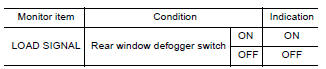
Is the inspection result normal?
YES >> GO TO 2.
NO >> Go to EC, "Diagnosis Procedure".
2.CHECK LIGHTING SWITCH FUNCTION
Check "LOAD SIGNAL" indication under the following conditions.
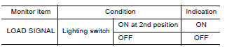
Is the inspection result normal?
YES >> GO TO 3.
NO >> Go to EC, "Diagnosis Procedure".
3.CHECK HEATER FAN CONTROL SWITCH FUNCTION
Select "HEATER FAN SW" and check indication under the following conditions
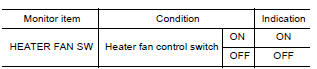
Is the inspection result normal?
YES >> INSPECTION END
NO >> Go to EC, "Diagnosis Procedure".
Diagnosis Procedure
1.INSPECTION START
Confirm the malfunctioning circuit (rear window defogger, headlamp or heater fan). Refer to EC, "Component Function Check".
Which circuit is related to the incident?
Rear window defogger>>GO TO 2
Headlamp>>GO TO 3.
Heater fan>>GO TO 4.
2.CHECK REAR WINDOW DEFOGGER SYSTEM
Perform trouble diagnosis of rear window defogger system. Refer to DEF, "Work Flow".
>> INSPECTION END
3.CHECK HEADLAMP SYSTEM
Perform trouble diagnosis of headlamp system. Refer to EXL, "Work Flow".
>> INSPECTION END
4.CHECK AIR CONDITIONING SYSTEM
Perform trouble diagnosis of air conditioning system. Refer to HA, "Workflow".
>> INSPECTION END
 Cooling fan
Other materials:
P2858 Clutch B pressure
DTC Logic
DTC DETECTION LOGIC
DTC
Trouble diagnosis name
DTC detection condition
Possible causes
P2858
Clutch B pressure engagement
performance
The auxiliary gearbox gear ratio is 2.232 or
more for the auxiliary gearbox 2GR ratio continuously
for 5 seconds ...
Torsion bar
TORSION BAR : Removal and Installation
REMOVAL
Remove torsion bar clamp.
Support trunk lid with a suitable tool.
WARNING:
Bodily injury may occur if trunk lid is not supported properly when removing the
torsion bars.
3. Apply a torsion bar wrench (A) to ...
Categories
- Manuals Home
- Nissan Versa Owners Manual
- Nissan Versa Service Manual
- Video Guides
- Questions & Answers
- External Resources
- Latest Updates
- Most Popular
- Sitemap
- Search the site
- Privacy Policy
- Contact Us

0.0055