Nissan Versa (N17): Starter motor
Exploded View
REMOVAL AND INSTALLATION
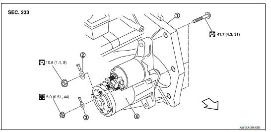
1. Cylinder block 2. "B" terminal harness 3. "S" terminal harness
4. Starter motor  Front
Front
DISASSEMBLY AND ASSEMBLY
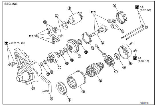
1. Magnetic switch assembly 2. Adjusting plate 3. Shift lever set 4. Center bracket (A) 5. Yoke assembly 6. Armature assembly 7. Brush holder assembly 8. Thrust washer 9. Rear cover assembly 10. Internal gear 11. Planetary gear 12. Pinion shaft 13. Packing 14. Thrust washer 15. Center bracket (C) 16. E-ring 17. Pinion assembly 18. Pinion stopper 19. Pinion stopper clip 20. Rubber seal 21. Gear case assembly
Removal and Installation
REMOVAL
- Disconnect the battery cable from the negative terminal. Refer to PG, "Removal and Installation".
- Remove air duct (inlet). Refer to EM, "Removal and Installation".
- Remove "S" terminal nut and "S" terminal harness.
- Remove "B" terminal nut and "B" terminal harness.
- Remove oil filter. Refer to LU, "Removal and Installation".
- Remove starter motor bolts.
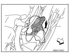
- Remove starter motor from underneath the vehicle.
CAUTION: Be careful to not damage surrounding parts when removing starter motor from the vehicle.
 : Front
INSTALLATION
Installation is in the reverse order of removal.
CAUTION:
- Be careful to tighten starter bolts, "S" terminal nut and "B" terminal nut to the specified torque.
- Install oil filter. Refer to LU, "Removal and Installation".
- Clean battery terminals and battery cables to remove corrosion prior to connecting.
- Ensure the battery cables are tightened to the specified torque.
NOTE: Reset electronic systems as necessary.
Inspection and Adjustment
INSPECTION
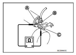
Magnetic Switch Check
- Disconnect the battery cable from the negative terminal. Refer to PG "Removal and Installation".
- Disconnect "M" terminal of starter motor.
- Test continuity between "S" terminal (A) and switch body.
(B): "B" terminal (C): "C" terminal
- Replace magnetic switch if continuity does not exist.
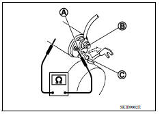
4. Test continuity between "S" terminal (A) and "M" terminal (C). (B): "B" terminal
- Replace magnetic switch if continuity does not exist.
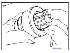
Pinion/Clutch Check
- Inspect pinion teeth.
- Replace pinion if teeth are worn or damaged. (Also check condition of ring gear teeth.)
- Inspect planetary gear teeth.
- Replace planetary gear if teeth are worn or damaged. (Also check condition of armature shaft gear teeth.)
- Check to see if pinion locks in one direction and rotates smoothly in the opposite direction.
- Replace pinion assembly if it is locked or rotated in both directions or unusual resistance is evident.
Brush Check
- Check brushes for excessive wear.
Minimum length of brush : Refer to STR
- Replace brush holder assembly if the measurement value is less than the specified value.
Brush Spring Check
- Check brush spring tension with brush spring detached from brush.
Spring tension (with new brush) : Refer to
- Replace brush holder assembly if the measurement value is less than the specified value.
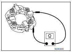
Brush Holder Check
- Perform insulation test between brush holder (positive side) and its base (negative side).
- Replace brush holder assembly if continuity does not exist.
- Check brush to see if it moves smoothly.
- If sliding surface is dirty, clean it.
- If brush holder is bent or damaged, replace brush holder assembly.
Yoke Check
Magnet is secured to yoke by bonding agent. Check magnet for cracks and to ensure it is secured to yoke. If damaged, replace yoke assembly.
CAUTION: Do not clamp yoke in a vise or strike it with a hammer.
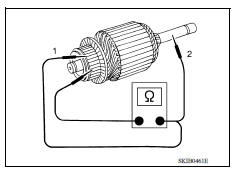
Armature Check
- Test continuity between two segments side by side.
- Replace armature assembly if continuity does not exist (1).
- Test insulation between each commutator bar and shaft.
- Replace armature assembly if continuity exists (2).
3. Check commutator surface.
- Clean commutator with No. 500 - 600 emery paper.
4. Check diameter of commutator.
- Replace armature assembly if the measurement value is less than the specified value.
Commutator minimum diameter : Refer to STR
5. Check depth of insulating mold from commutator surface.
- Undercut to 0.5 to 0.8 mm (0.020 to 0.031 in) if the depth is 0.2 mm (0.008 in) or less.
PINION PROTRUSION LENGTH ADJUSTMENT
1. Apply battery power to the magnetic switch.
2. Push the pinion back to remove the slack and measure clearance "L" between the front edge of the pinion and the pinion stopper.
Clearance "L" : Refer to STR
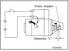
3. If the measurement value is not within specifications, adjust using the adjustment plate.
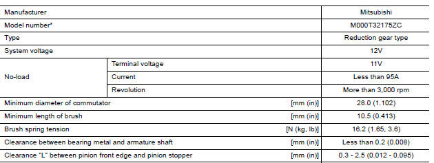
SERVICE DATA AND SPECIFICATIONS (SDS)
Starter Motor
 S connector circuit
Description The starter motor magnetic switch is supplied with power when the ignition switch is turned to the START position while the selector lever is in the P (Park) or N (Neutral) position. ...
Precautions
Precaution for Supplemental Restraint System (SRS) "AIR BAG" and "SEAT BELT PRE-TENSIONER" The Supplemental Restraint System such as "AIR BAG" and "SEAT BELT PRE-TENSIONER", us ...
Other materials:
Installing front license plate
Use the following steps to mount the front license
plate:
Before mounting the license plate, confirm that
the following parts are enclosed in the plastic
bag:
License plate bracket
License plate bracket screws x 2
Screw grommets x 2
1. Hold the license plate bracket 1 and make
a ...
Fluid cooler & fluid warmer system
FLUID COOLER & FLUID WARMER SYSTEM :
System Description
CVT FLUID COOLER SCHEMATIC
COMPONENT DESCRIPTION
CVT Oil Warmer
The CVT oil warmer (1) is installed on the front part of transaxle
assembly.
When engine is started while engine and CVT are cold, engine
coolant temperatur ...
Categories
- Manuals Home
- Nissan Versa Owners Manual
- Nissan Versa Service Manual
- Video Guides
- Questions & Answers
- External Resources
- Latest Updates
- Most Popular
- Sitemap
- Search the site
- Privacy Policy
- Contact Us

0.0057