Nissan Versa (N17): Front door speaker
Diagnosis Procedure
Regarding Wiring Diagram information, refer to AV "Wiring Diagram".
1.CONNECTOR CHECK
Check the audio unit and speaker connectors for the following:
- Proper connection
- Damage
- Disconnected or loose terminals
Is the inspection result normal?
YES >> GO TO 2
NO >> Repair the terminals or connectors.
2.CHECK FRONT DOOR SPEAKER SIGNAL CIRCUIT CONTINUITY
1. Disconnect audio unit connector M44 and suspect front door speaker connector.
2. Check continuity between audio unit connector M44 and suspect front door
speaker connector.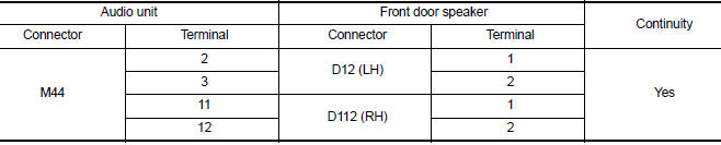
3. Check continuity between audio unit connector M44 and ground.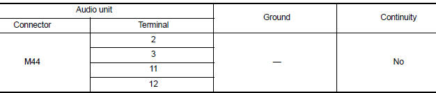
Is the inspection result normal?
YES >> GO TO 3
NO >> Repair or replace harness or connectors.
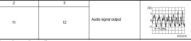
3.CHECK FRONT DOOR SPEAKER SIGNAL
1. Connect audio unit connector M44 and suspect front door speaker connector.
2. Turn ignition switch to ACC.
3. Push audio unit POWER switch.
4. Check signal between the terminals of audio unit connector M44.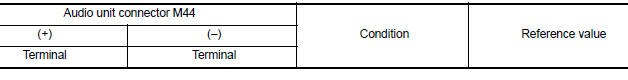
Is the inspection result normal?
YES >> Replace front door speaker. Refer to AV "Removal and Installation".
NO >> Replace audio unit. Refer to AV "Removal and Installation".
 Power supply and ground circuit
Rear door speaker
Diagnosis Procedure Regarding Wiring Diagram information, refer to AV "Wiring Diagram". 1.CONNECTOR CHECK Check the audio unit and speaker connectors for the following: Proper conne ...
Other materials:
Preparation
Special Service Tools
The actual shapes of KentMoore tools may differ from those of special
service tools illustrated here.
Tool number
(KentMoore No.)
Tool name
Description
ST25051001
(J256951)
Oil pressure gauge &nbs ...
P0713 Transmission fluid temperature
sensor A
DTC Logic
DTC DETECTION LOGIC
DTC
Trouble diagnosis name
DTC detection condition
Possible causes
P0713
Transmission Fluid Temperature
Sensor "A" Circuit High
Under the following diagnosis
conditions, the A/T fluid temperature
identified by TCM is −
...
Categories
- Manuals Home
- Nissan Versa Owners Manual
- Nissan Versa Service Manual
- Video Guides
- Questions & Answers
- External Resources
- Latest Updates
- Most Popular
- Sitemap
- Search the site
- Privacy Policy
- Contact Us

0.0106