Nissan Versa (N17): Fuel level sensor unit
Disassembly and Assembly
Fuel Level Sender Unit
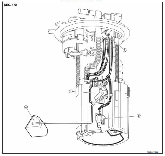
1. Harness connectors 2. Level sending unit module 3. Fuel temperature sensor 4. Float arm assembly
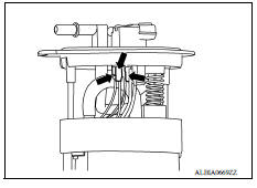
Disassembly
NOTE: Before disassembly, note the proper placement of the wires to the correct terminals and correct wire routing to the terminals.
- Disconnect the red, white, and double black wire connectors.
- Press the tabs on the terminals to release the locking tabs.
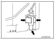
2. Release the two clips and remove the fuel temperature sensor from the pump assembly.
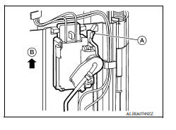
3. Release the tab (A) and slide the level sending unit module and float arm assembly up (B) to remove.
Assembly
Assembly is in the reverse order of disassembly.
NOTE:
- Ensure proper placement of the wires to the correct terminals and correct wire routing to the terminals.
- After connecting terminals, ensure they are securely locked and can not be pulled out.
- When installing the level sending unit, push down until the tab is locked into place.
SERVICE DATA AND SPECIFICATIONS (SDS)
Fuel Tank
STANDARD AND LIMIT
| Fuel tank capacity | Approx. 41.0  (10-7/8 US
gal, 9 Imp gal) (10-7/8 US
gal, 9 Imp gal) |
| Fuel recommendation | Refer to GI, "Fuel (Regular Unleaded Gasoline Recommended) HR16DE". |
 EVAP control system pressure sensor
Exploded View 1. EVAP control system pressure sensor 2. O-ring 3. EVAP canister Removal and Installation NOTE: The EVAP canister system pressure sensor can be removed without removing the E ...
Precautions
Precaution for Supplemental Restraint System (SRS) "AIR BAG" and "SEAT BELT PRE-TENSIONER" The Supplemental Restraint System such as "AIR BAG" and "SEAT BELT PRE-TENSIONER", us ...
Other materials:
Car phone or CB radio
When installing a CB, ham radio or car phone in
your vehicle, be sure to observe the following
precautions; otherwise, the new equipment may
adversely affect the engine control system and
other electronic parts.
WARNING
A cellular phone should not be used for
any purpose while driving so ...
Towing your vehicle
When towing your vehicle, all State (Provincial in
Canada) and local regulations for towing must be
followed. Incorrect towing equipment could damage
your vehicle. Towing instructions are available
from a NISSAN dealer. Local service operators
are generally familiar with the applicable laws
an ...
Categories
- Manuals Home
- Nissan Versa Owners Manual
- Nissan Versa Service Manual
- Video Guides
- Questions & Answers
- External Resources
- Latest Updates
- Most Popular
- Sitemap
- Search the site
- Privacy Policy
- Contact Us

0.0069