Nissan Versa (N17): Transmission assembly
Exploded View
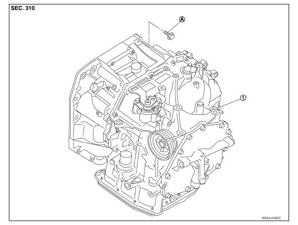
1. Transaxle assembly
A. : Tightening must be done following the installation procedure. Refer to TM "Removal and Installation".
Removal and installation
WARNING:
- Do not open the radiator cap or drain plug when the engine is hot. Hot liquid may spray out, causingserious injury.
- Perform these steps after the coolant temperature has cooled sufficiently.
NOTE:
- When replacing the TCM and transaxle assembly as a set, replace the transaxle assembly first and thenreplace the TCM. Refer to TM "Description".
- When replacing components such as hoses, tubes/lines, etc., cap or plug openings to prevent fluid fromspilling.
REMOVAL
- Remove the TCM. Refer to TM "Removal and Installation".
- Remove the battery plate.
- Remove the air duct and air cleaner case. Refer to EM "Removal and Installation".
- Disconnect the harness connectors from the following components and remove the harness from the transaxle.
- A/T unit. Refer to TM "Removal and Installation Procedure for A/T Assembly Connector".
- Transmission range switch
- Input speed sensor
- Output speed sensor
- Crankshaft position sensor. Refer to EM "Exploded View".
- Ground
- Remove the control cable from the transaxle assembly. Refer to TM "Removal and Installation".
- Disconnect the fluid cooler hose from the fluid cooler tube. Refer to TM "Removal and Installation".
- Remove the left and right drive shafts. Refer to FAX "Removal and Installation".
- Remove the drive shaft heat insulator.
- Remove starter motor. Refer to STR "Removal and Installation".
- Reposition the fender protectors out of the way. Refer to EXT "Removal and Installation".
- Rotate the crankshaft and remove the nuts that secure the drive plate to
the torque converter.
CAUTION: Rotate crankshaft clockwise (as viewed from the front of the engine).
- Remove the rear torque rod. Refer to EM "Exploded View".
- Set a transmission jack under the transaxle assembly.
CAUTION: Be careful not to contact the drain plug when setting the transmission jack.
- Set a transmission jack under the engine assembly.
CAUTION: Be careful not to contact the drain plug when setting the transmission jack.
- Remove the left engine mounting insulator. Refer to EM "Exploded View".
- Remove the left engine mounting bracket (LH). Refer to EM "Exploded View".
- Remove the bolts that fasten the transaxle assembly and engine assembly.
- Remove the transaxle assembly from the vehicle.
CAUTION: Do not drop the torque converter.
INSTALLATION
Installation is in the reverse order of removal.
CAUTION:
- Do not reuse O-ring or copper sealing washers.
- Apply ATF to the O-ring.
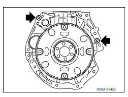
- When installing the transaxle assembly onto the engine assembly,
check the engagement of the dowel pins (
 ).
).
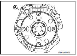
- When using suitable tool (A) for alignment, install it to the alignment stud bolt used to align the torque converter to the drive plate.
- Rotate the crankshaft so that the alignment hole (A) of drive plate
aligns with the position of the torque converter alignment stud bolt.
CAUTION:
- Rotate the crankshaft clockwise (as viewed from the front of the engine).
- Be careful that torque converter stud bolts are aligned to the drive plate holes. Otherwise the stud bolts contact the drive plate.
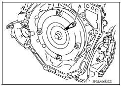
- Insert the alignment stud bolt of torque converter into the alignment
hole of the drive plate, aligning the drive plate holes with the
torque converter stud bolts.
CAUTION: Be careful not to strike the drive plate with the torque converter stud bolts.
- When installing the torque converter nuts, temporarily tighten the nuts. Then, after installing the engine and transaxle assembly bolts tighten the nuts to the specified torque.
Tightening torque : 51 N*m (5.2 kg-m, 38 ft-lb)
CAUTION:
- Rotate the crankshaft clockwise (as viewed from the front of the engine).
- Check the tightening torque for the crankshaft pulley bolts after the bolts fastening the drive plate and torque converter have been tightened and the crankshaft pulley bolts have been secured.
Refer to EM "Exploded View".
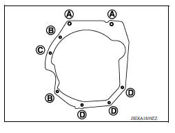
- Install the transaxle assembly and engine assembly bolts according to the following standards.
Inspection and adjustment
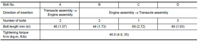
INSPECTION BEFORE INSTALLATION
Check the distance (A) between the converter housing and torque converter
(B) : Scale
(C) : Straightedge
Dimension (A) : TM "Torque Converter"
INSPECTION AFTER INSTALLATION
Check the following items:
-
A/T fluid leakage, refer to TM "Inspection".
-
For the A/T positions, refer to TM "Inspection and Adjustment"
-
Start the engine and check for coolant leakage from the parts which are removed and reinstalled.
ADJUSTMENT AFTER INSTALLATION
-
Check the A/T fluid level. Refer to TM "Adjustment".
-
Perform "TRANSAXLE ASSEMBLY REPLACEMENT". Refer to TM "Description".
 Fluid cooler tube
Exploded View 1. Fluid cooler tube A 2. Copper sealing washer 3. Fluid cooler tube B 4. Bolt 5. Transaxle assembly Removal and Installation WARNING: Do not open the radiator cap or drain p ...
Service data and specifications
(SDS)
General Specification CAUTION: Use only Genuine NISSAN Matic S ATF. Do not mix with other ATF. Using ATF other than Genuine NISSAN Matic S ATF will cause deterioration of driv ...
Other materials:
U1117 Lost communication (ABS)
DTC Logic
DTC DETECTION LOGIC
DTC
Trouble diagnosis name
DTC detection condition
Possible causes
U1117
Lost Communication With ABS
When the ignition switch is ON,
TCM is unable to receive the
CAN communications signal
from ABS actuator control unit
cont ...
P0974 Shift solenoid A
DTC Logic
DTC DETECTION LOGIC
DTC
Trouble diagnosis name
DTC detection condition
Possible causes
P0974
Shift Solenoid "A" Control Circuit
High
The following diagnosis conditions
are met, and the TCM select
switch ON-OFF solenoid
valve monitor value is OF ...
Categories
- Manuals Home
- Nissan Versa Owners Manual
- Nissan Versa Service Manual
- Video Guides
- Questions & Answers
- External Resources
- Latest Updates
- Most Popular
- Sitemap
- Search the site
- Privacy Policy
- Contact Us

0.0054