
Nissan Versa (N17): Inside key antenna
Instrument center
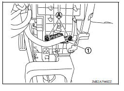
INSTRUMENT CENTER : Removal and Installation
REMOVAL
1. Remove the instrument lower center panel. Refer to IP "Removal and Installation".
2. Remove screws (A) and the inside key antenna (instrument center) (1).
INSTALLATION
Installation is in the reverse order of removal.
Console
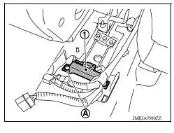
CONSOLE : Removal and Installation
REMOVAL
1. Remove the center console assembly. Refer to IP "Removal and Installation".
2. Remove clips (A) and the inside key antenna (console) (1).
INSTALLATION
Installation is in the reverse order of removal.
Trunk room
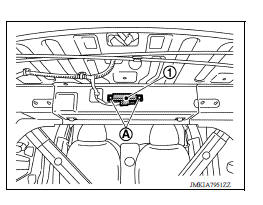
TRUNK ROOM : Removal and Installation
REMOVAL
Remove clips (A) and the inside key antenna (trunk room) (1).
INSTALLATION
Installation is in the reverse order of removal.
 Door switch
Exploded View 1. Door switch 2. Door switch bolt Removal and Installation REMOVAL 1. Remove the door switch bolt (A). 2. Disconnect the harness connector and remove door switch (1). INST ...

Other materials:
Noise, vibration and harshness (NVH) troubleshooting
NVH troubleshooting Chart
Locate the area where noise occurs.
Confirm the type of noise.
Specify the operating condition of engine.
Check specified noise source
If necessary, repair or replace these parts.
Location
of noise
Type of
noise
Operating condition of
...
Intake manifold
Exploded View
1. EVAP canister purge volume control
solenoid valve
2. Hose clamp 3. Vacuum hose
4. PCV hose 5. Hose clamp 6. Intake manifold support
7. Gasket 8. Intake manifold 9. Electric throttle control actuator
10. Gasket 11. EVAP service port
A. To air duct B. To centralized underf ...
Categories
- Manuals Home
- Nissan Versa Owners Manual
- Nissan Versa Service Manual
- Video Guides
- Questions & Answers
- External Resources
- Latest Updates
- Most Popular
- Sitemap
- Search the site
- Privacy Policy
- Contact Us

0.0074