Nissan Versa (N17): Instrument panel
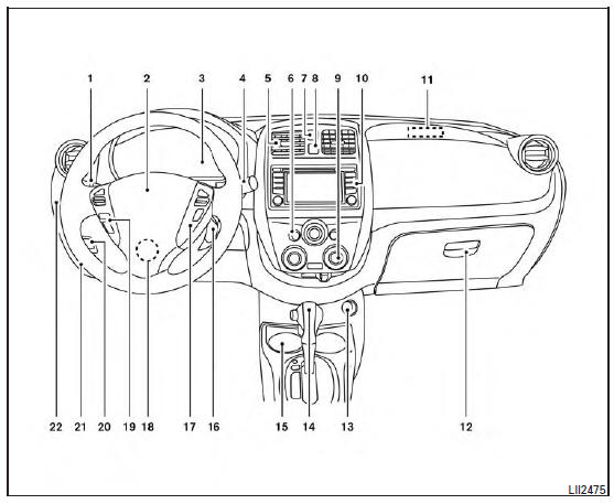
1. Headlight/turn signal switch/fog light switch (if so equipped)
2. Driver's supplemental air bag (P. 1-39) Horn
3. Meters and gauges. Warning and indicator lights
4. Wiper and washer switch
5. Vents
6. Rear window defroster switch
7. Front passenger air bag status light
8. Hazard warning flasher switch
9. Climate controls
10. Audio system
11. Passenger's supplemental air bag
12. Glove box
13. Power outlet
14. Shift lever
15. Cup holders
16. Ignition switch (if so equipped). Push-button ignition switch (if so equipped)
17. Cruise control switches (if so equipped)
18. Tilt steering
19. Audio control switches. Bluetooth Hands-Free Phone System switches
20. Vehicle Dynamic Control (VDC) OFF switch
21. Fuel-filler door release lever. Hood release lever
22. Electronic outside rearview mirror control switch
Refer to the page number indicated in parentheses for operating details.
 Passenger compartment
1. Interior light 2. Sun visors 3. Map light (if so equipped) 4. Rearview mirror 5. Glove box 6. Parking brake Refer to the page number indicated in parentheses for operating details. ...
Engine compartment check locations
HR16DE Engine 1. Drive belt location 2. Engine oil filler cap 3. Air cleaner 4. Brake and clutch (if so equipped) fluid reservoir 5. Fusible link 6. Battery 7. Engine coolant reservoir 8. ...
Other materials:
Description
Engine Cooling System
M/T models
CVT and A/T models
Engine Cooling System Schematic
M/T models
CVT and A/T models
OVERHEATING CAUSE ANALYSIS
Troubleshooting Chart
Symptom
Check items
Cooling system
parts
malfunction
Poor heat transfer
...
B terminal circuit
Description
Terminal "B" is constantly supplied with battery power.
Diagnosis Procedure
Regarding Wiring Diagram information, refer to STR, "Wiring Diagram - With
Intelligent Key System" or
STR, "Wiring Diagram - Without Intelligent Key System".
CAUTION: Perform diagnosis ...
Categories
- Manuals Home
- Nissan Versa Owners Manual
- Nissan Versa Service Manual
- Video Guides
- Questions & Answers
- External Resources
- Latest Updates
- Most Popular
- Sitemap
- Search the site
- Privacy Policy
- Contact Us

0.0052