Nissan Versa (N17): Intake valve timing control
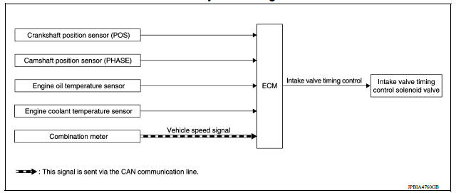
Intake valve timing control : System Diagram
Intake valve timing control : system description
INPUT/OUTPUT SIGNAL CHART
| Sensor | Input signal to ECM | ECM function | Actuator |
| Crankshaft position sensor (POS) | Engine speed*1 Piston position | Intake valve timing control | Intake valve timing control solenoid valve |
| Camshaft position sensor (PHASE) | |||
| Engine oil temperature sensor | Engine oil temperature | ||
| Engine coolant temperature sensor | Engine coolant temperature | ||
| Combination meter | Vehicle speed*2 |
*1: ECM determines the start signal status by the signals of engine speed and battery voltage.
*2: This signal is sent to the ECM through CAN communication line.
SYSTEM DESCRIPTION
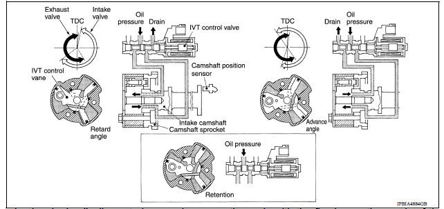
This mechanism hydraulically controls cam phases continuously with the fixed operating angle of the intake valve.
The ECM receives signals such as crankshaft position, camshaft position, engine speed, engine oil temperature and engine coolant temperature. Then, the ECM sends ON/OFF pulse duty signals to the intake valve timing (IVT) control solenoid valve depending on driving status. This makes it possible to control the shut/open timing of the intake valve to increase engine torque in low/mid speed range and output in highspeed range.
 Evaporative emission system
EVAPORATIVE EMISSION SYSTEM : System Diagram EVAPORATIVE EMISSION SYSTEM : System Description INPUT/OUTPUT SIGNAL CHART Sensor Input signal to ECM ECM function Actuator ...
Exhaust valve timing control
Exhaust valve timing control : system diagram Exhaust valve timing control : system description INPUT/OUTPUT SIGNAL CHART Sensor Input signal to ECM ECM function Actuator ...
Other materials:
Starting the engine (models with NISSAN Intelligent Key system)
1. Apply the parking brake.
2. Move the shift lever to P (Park) or N (Neutral).
P (Park) is recommended.
The starter is designed not to operate if
the shift lever is in any of the driving
positions.
3. Push the ignition switch to the ON position.
Depress the brake pedal and push the ...
Additional service when replacing
ECM
Description
When replacing ECM, the following procedure must be performed.
PROGRAMMING OPERATION
NOTE:
After replacing with a blank ECM, programming is required to write ECM
information. Be sure to follow the procedure
to perform the programming.
Work Procedure
1.CHECK ECM PART NUMBER
Che ...
Categories
- Manuals Home
- Nissan Versa Owners Manual
- Nissan Versa Service Manual
- Video Guides
- Questions & Answers
- External Resources
- Latest Updates
- Most Popular
- Sitemap
- Search the site
- Privacy Policy
- Contact Us

0.0058