Nissan Versa (N17): Intelligent key system
INTELLIGENT KEY SYSTEM : System Description
SYSTEM DIAGRAM
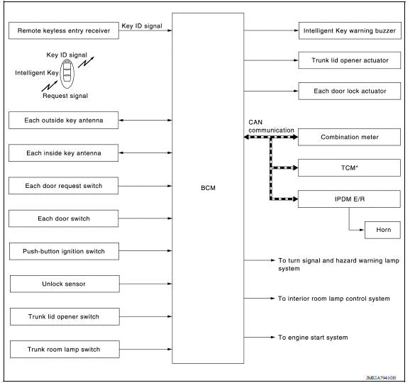
SYSTEM DESCRIPTION
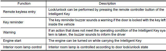
- The Intelligent Key system is a system that makes it possible to lock and unlock the door locks (door lock/ unlock function) by carrying the Intelligent Key, which operates based on the results of electronic ID verification using two-way communication between the Intelligent Key and the vehicle (BCM).
NOTE: The driver should always carry the Intelligent Key
- The settings for each function can be changed with CONSULT.
- If an Intelligent Key is lost, a new Intelligent Key can be registered. A maximum of 4 Intelligent Keys can be registered.
- It is possible to perform a diagnosis on the system and register an
Intelligent Key with CONSULT.
 System (power door lock system)
System Diagram System Description DOOR LOCK FUNCTION The door lock and unlock switch (driver side) is built into power window main switch. The door lock and unlock switch (pa ...
Door lock function
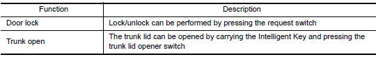
DOOR LOCK FUNCTION : System Description SYSTEM DIAGRAM DOOR REQUEST SWITCH OPERATION When pressing the request switch, it is possible to lock and unlock the door by carrying the Intelligent ...
Other materials:
Rear oil seal
REAR OIL SEAL : Removal and Installation
REMOVAL
Remove transaxle assembly.
Remove clutch cover and clutch disk (M/T models).
Remove flywheel (M/T models) or drive plate (A/T or CVT models).
Remove rear oil seal with a suitable tool.
CAUTION:
Be careful not to damage crankshaft an ...
Control linkage
Exploded View
1. Shifter lever A 2. Selector lever 3. Selector cable
4. Shifter cable 5. Cable mounting bracket 6. Tapping bolt
7. Bracket 8. Grommet 9. M/T shift selector assembly
10. Shift selector 11. Shift selector handle
Removal and Installation
REMOVAL
Move the shift selector to ...
Categories
- Manuals Home
- Nissan Versa Owners Manual
- Nissan Versa Service Manual
- Video Guides
- Questions & Answers
- External Resources
- Latest Updates
- Most Popular
- Sitemap
- Search the site
- Privacy Policy
- Contact Us

0.0051