Nissan Versa (N17): Lock-up control
LOCK-UP CONTROL : System Description
SYSTEM DIAGRAM
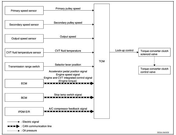
DESCRIPTION
- Controls for improvement of the transmission efficiency by engaging the torque converter clutch in the torque converter and eliminating slip of the converter. Achieves comfortable driving with slip control of the torque converter clutch.
- The oil pressure feed circuit for the torque converter clutch piston chamber is connected to the torque converter clutch control valve. The torque converter clutch control valve is switched by the torque converter clutch solenoid valve with the signal from TCM. This controls the oil pressure circuit, which is supplied to the torque converter clutch piston chamber, to the release side or engagement side.
- If the CVT fluid temperature is low or the vehicle is in fail-safe mode due to malfunction, lock-up control is prohibited.
Lock-up engagement
In lock-up engagement, the torque converter clutch solenoid valve makes the torque converter clutch control valve locked up to generate the lock-up apply pressure. This pushes the torque converter clutch piston for engagement.
Lock-up release condition
In lock-up release, the torque converter clutch solenoid valve makes the torque converter clutch control valve non-locked up to drain the lock-up apply pressure. This does not engage the torque converter clutch piston.
 Shift control
SHIFT CONTROL : System Description SYSTEM DIAGRAM DESCRIPTION To select the gear ratio that can give the driving force to meet driver's intent or vehicle situation, the vehicle driving con ...
Idle neutral control
IDLE NEUTRAL CONTROL : System Description SYSTEM DIAGRAM DESCRIPTION If a driver has no intention of starting the vehicle in D position, TCM operates the low brake solenoid valve and control ...
Other materials:
S connector circuit
Description
The starter motor magnetic switch is supplied with power when the ignition
switch is turned to the START position
while the selector lever is in the P (Park) or N (Neutral) position.
Diagnosis Procedure
Regarding Wiring Diagram information, refer to STR, "Wiring Diagram - Wit ...
Manual air conditioning system
MANUAL AIR CONDITIONING SYSTEM : System
Diagram
MANUAL AIR CONDITIONING SYSTEM : System
Description
The manual air conditioning system is controlled by a sequence of
functions from the front air control, BCM,
ECM, and IPDM E/R.
The fan speed of the front blower motor is change ...
Categories
- Manuals Home
- Nissan Versa Owners Manual
- Nissan Versa Service Manual
- Video Guides
- Questions & Answers
- External Resources
- Latest Updates
- Most Popular
- Sitemap
- Search the site
- Privacy Policy
- Contact Us

0.0097