Nissan Versa (N17): M&A Branch line circuit
Diagnosis Procedure
1.CHECK CONNECTOR
1. Turn the ignition switch OFF.
2. Disconnect the battery cable from the negative terminal.
3. Check the terminals and connectors of the combination meter for damage, bend and loose connection (unit side and connector side).
Is the inspection result normal?
YES >> GO TO 2.
NO >> Repair the terminal and connector.
2.CHECK HARNESS FOR OPEN CIRCUIT
1. Disconnect the connector of combination meter.
2. Check the resistance between the combination meter harness connector terminals.
NOTE: Check the vehicle type confirm the service information. Refer to MWI "Information".
- Models with Type A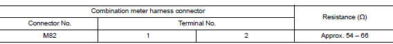
- Models with Type B 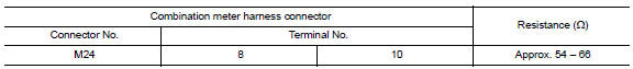
Is the measurement value within the specification?
YES >> GO TO 3.
NO >> Repair the combination meter branch line.
3.CHECK POWER SUPPLY AND GROUND CIRCUIT
Check the power supply and the ground circuit of the combination meter. Refer to the following.
- TYPE A: MWI "COMBINATION METER : Diagnosis Procedure"
- TYPE B: MWI "COMBINATION METER : Diagnosis Procedure"
Is the inspection result normal?
YES (Present error)>>Replace the combination meter. Refer to the following.
- TYPE A: MWI "Removal and Installation"
- TYPE B: MWI"Removal and Installation"
YES (Past error)>>Error was detected in the combination meter branch line.
NO >> Repair the power supply and the ground circuit.
 EPS Branch line circuit
Diagnosis Procedure 1.CHECK CONNECTOR 1. Turn the ignition switch OFF. 2. Disconnect the battery cable from the negative terminal. 3. Check the terminals and connectors of the EPS control unit f ...
STRG Branch line circuit
Diagnosis Procedure 1.CHECK CONNECTOR 1. Turn the ignition switch OFF. 2. Disconnect the battery cable from the negative terminal. 3. Check the terminals and connectors of the steering angle sen ...
Other materials:
Servicing air conditioner
The air conditioner system in your NISSAN vehicle
is charged with a refrigerant designed with
the environment in mind.
This refrigerant does not harm the earth's
ozone layer.
Special charging equipment and lubricant is required
when servicing your NISSAN air conditioner.
Using improper ...
Clutch piping
Exploded View
1. CSC (Concentric Slave Cylinder) 2. Clutch tube 3. Clutch damper
4. Bracket 5. Master cylinder
Hydraulic Layout
1. Clutch tube 2. Lock pin 3. CSC (concentric slave cylinder)
4. Clutch damper 5. Master cylinder 6. Clutch pedal
Removal and Installation
CAUTION:
Do not ...
Categories
- Manuals Home
- Nissan Versa Owners Manual
- Nissan Versa Service Manual
- Video Guides
- Questions & Answers
- External Resources
- Latest Updates
- Most Popular
- Sitemap
- Search the site
- Privacy Policy
- Contact Us

0.0057