
Nissan Versa (N17): Oil pan (lower)
Exploded View
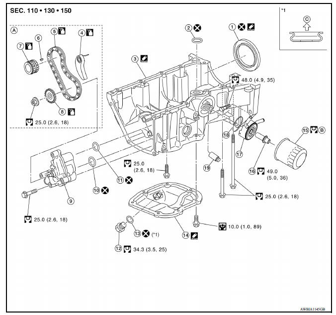
1. Rear oil seal 2. Oring 3. Oil pan (upper) 4. Oil pump chain tensioner (for oil pump drive chain) 5. Oil pump drive chain 6. Crankshaft key 7. Crankshaft sprocket 8. Oil pump sprocket 9. Oil pump 10. Oring 11. Oring 12. Oil pan drain plug 13. Drain plug washer 14. Oil pan (lower) 15. Oil filter 16. Connector bolt 17. Oil cooler 18. Oring 19. Relief valve
Removal and Installation
REMOVAL
WARNING:
- Be careful not to get burned, engine coolant and engine oil may be hot.
- Prolonged and repeated contact with used engine oil may cause skin cancer; avoid direct skin contact with used oil. If skin contact is made, wash thoroughly with soap or hand cleaner as soon as possible.
- Drain engine oil.
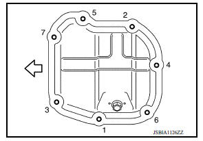
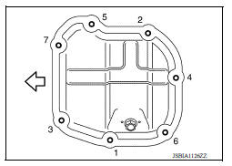
- Loosen bolts in reverse order as shown.
 : Engine front
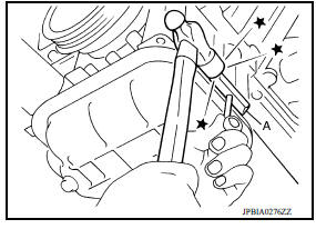
- Insert Tool (A) between oil pan (upper) and oil pan (lower).
Tool number : KV10111100 (J37228)
CAUTION:
- Do not damage mating surfaces.
- Do not insert a screwdriver. This damages the mating surfaces.
- Slide the Tool (A) by tapping on the side of tool with a suitable tool to loosen the oil pan (lower).
- Remove oil pan (lower).
INSPECTION AFTER REMOVAL
Clean debris from oil pan (lower) and from the strainer.
INSTALLATION
CAUTION:
Do not reuse Orings or washers.
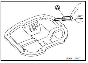
1. Use a scraper (A) to remove old liquid gasket from mating surfaces.
- Also remove old liquid gasket from mating surface of oil pan (upper).
- Remove old liquid gasket from the bolt holes and threads.
CAUTION:
Do not scratch or damage the mating surface when cleaning off old liquid gasket.
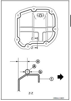
2. Apply a continuous bead of liquid gasket (A) with a tube presser as shown.
(1) : Oil pan (lower)
(a) : 7.5 9.5 mm (0.295 0.374 in)
(b) : 4.0 5.0 mm (0.157 0.197 in) diameter
 : Engine outside
Use Genuine Silicone RTV Sealant or equivalent.
CAUTION:
- The components must be installed within 5 minutes of the liquid gasket application.
- Do not confirm torque after the 5 minutes have elapsed.
- Then allow 30 minutes for the liquid gasket to set before adding oil to the engine.
3. Tighten bolts in numerical order as shown.
 : Engine front
4. Install oil pan drain plug.
- Refer to the figure for installation direction of drain plug washer.
CAUTION:
- Installation should be done within 5 minutes after applying liquid gasket.
- Do not fill the engine with oil for at least 30 minutes after the oil pan (lower) is installed to allow the sealant to cure.
5. Add the specified oil after waiting for at least 30 minutes.
INSPECTION AFTER INSTALLATION
- Before starting engine, check oil/fluid levels, including engine coolant and engine oil. If less than required quantity, fill to the specified level.
- Use procedure below to check for fuel leakage.
- Turn ignition switch ON (with engine stopped). With fuel pressure applied to fuel piping, check for fuel leakage at connection points.
- Start engine. With engine speed increased, check again for fuel leakage at connection points.
- Run engine to check for unusual noise and vibration.
NOTE:
If hydraulic pressure inside timing chain tensioner drops after removal and installation, slack in the guide may generate a pounding noise during and just after engine start. However, this is normal. Noise will stop after hydraulic pressure rises.
- Warm up engine thoroughly to make sure there is no leakage of fuel, exhaust gas, or any oils/fluids including engine oil and engine coolant.
- Bleed air from passages in lines and hoses, such as in cooling system.
- After cooling down engine, again check oil/fluid levels including engine oil and engine coolant. Refill to specified level, if necessary.
- Summary of the inspection items:
| Item | Before starting engine | Engine running | After engine stopped | |
| Engine coolant | Level | Leakage | Level | |
| Engine oil | Level | Leakage | Level | |
| Transmission/ transaxle fluid | A/T and CVT Models | Leakage | Level/Leakage | Leakage |
| M/T Models | Level/Leakage | Leakage | Level/Leakage | |
| Other oils and fluids* | Level | Leakage | Level | |
| Fuel | Leakage | Leakage | Leakage | |
| Exhaust gas | Leakage | |||
*Power steering fluid, brake fluid, etc.
 Exhaust manifold
Exploded View 1. Exhaust manifold cover 2. Harness bracket 3. Airfuel ratio sensor 1 4. Exhaust manifold stay 5. Heat insulator 6. Exhaust manifold 7. Exhaust manifold cover 8. Gasket : Engi ...
Fuel injector and fuel tube
Exploded View 1. Stud bolt 2. Oring (green) 3. Fuel injector (front) 4. Clip 5. Fuel injector (rear) 6. Oring (black) 7. Fuel tube protector 8. Fuel tube 9. Clamp 10. Quick connector cap (eng ...
Other materials:
Power outlets
Instrument panel
Console (if so equipped)
The power outlets are for powering electrical
accessories such as cellular telephones. The
outlets are rated at 12 volt, 120W (10A) maximum.
CAUTION
The outlet and plug may be hot during
or immediately after use.
Only certain power outlets ...
Servicing air conditioner
The air conditioner system in your NISSAN vehicle
is charged with a refrigerant designed with
the environment in mind.
This refrigerant does not harm the earth's
ozone layer.
Special charging equipment and lubricant is required
when servicing your NISSAN air conditioner.
Using improper ...
Categories
- Manuals Home
- Nissan Versa Owners Manual
- Nissan Versa Service Manual
- Video Guides
- Questions & Answers
- External Resources
- Latest Updates
- Most Popular
- Sitemap
- Search the site
- Privacy Policy
- Contact Us

0.0112