Nissan Versa (N17): P0705 Transmission range switch A
DTC Logic
DTC DETECTION LOGIC
| DTC | Trouble diagnosis name | DTC detection condition | Possible causes |
| P0705 | Transmission Range Sensor "A" Circuit Malfunction (PRNDL input) | The following diagnosis conditions
are met and 2 or more position
signals are ON at the
same time for 5 seconds or
more. - Diagnosis condition - TCM power supply voltage: 10 V <TCM power supply voltage <16 V |
|
DTC CONFIRMATION PROCEDURE
1.PREPARATION BEFORE WORK
If another "DTC CONFIRMATION PROCEDURE" occurs just before, turn the ignition switch OFF and wait for at least 10 seconds, then perform the next test.
>> GO TO 2.
2.CHECK DTC DETECTION
- Turn ignition switch ON.
- Shift the selector lever to the entire position from P to 1. (Hold the selector lever at each position for 10 seconds or more.)
- Check the first trip DTC.
Is "P0705" detected?
YES >> Go to TM, "Diagnosis Procedure".
NO >> INSPECTION END
Diagnosis Procedure
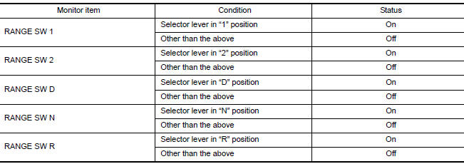
1.CHECK TCM INPUT SIGNALS
With CONSULT
- Turn ignition switch ON.
- Select "TRANSMISSION" "DATA MONITOR".
- Select the "D position switch", "N position switch", "R position switch", "P position switch", "2 position switch", and "1 position switch".
- Shift the selector lever to the entire position from P to 1, and check
the ON/OFF operation of each monitor
item.

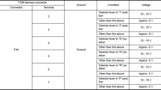
Without CONSULT.
- Turn ignition switch OFF.
- Disconnect the TCM connector.
- Turn ignition switch ON.
- Shift the selector lever to the entire position from P to 1, and check
the voltage between the TCM harness
connector terminal and ground.
Is the check result normal?
YES >> Check intermittent incident. Refer to GI, "Intermittent Incident".
NO-1 [D position SW is "On" when selector is not in D position. (Or, connector terminal 4 is at 10 - 16 V.)]>> GO TO 2.
NO-2 [N position SW is "On" when selector is not in N position. (Or, connector terminal 5 is at 10 - 16 V.)]>> GO TO 4.
NO-3 [R position SW is "On" when selector is not in R position. (Or, connector terminal 6 is at 10 - 16 V.)]>> GO TO 6.
NO-4 [P position SW is "On" when selector is not in P position. (Or, connector terminal 7 is at 10 - 16 V.)]>> GO TO 8.
NO-5 [2 position SW is "On" when selector is not in 2 position. (Or, connector terminal 3 is at 10 - 16 V.)]>> GO TO 10.
NO-6 [1 position SW is "On" when selector is not in 1 position. (Or, connector terminal 2 is at 10 - 16 V.)]>> GO TO 12.
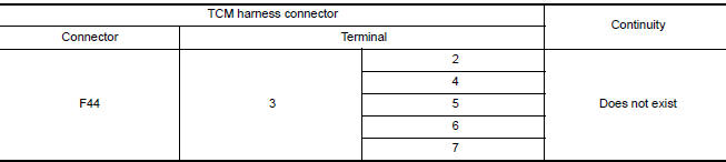
2.CHECK D POSITION SW CIRCUIT (CHECK 1)
- Turn ignition switch OFF.
- Disconnect the TCM connector.
- Check the continuity between the TCM harness connector terminals.
Is the check result normal?
YES >> GO TO 3.
NO >> Repair or replace the malfunctioning parts.
3.CHECK D POSITION SW CIRCUIT (CHECK 2)
- Disconnect the transmission range switch connector.
- Turn the ignition switch ON.
- Check the voltage between the TCM harness connector and ground.
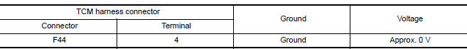
Is the check result normal?
YES >> GO TO 14.
NO >> Repair or replace the malfunctioning parts.
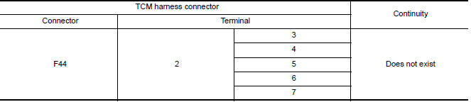
4.CHECK N POSITION SW CIRCUIT (CHECK 1)
- Turn ignition switch OFF.
- Disconnect the TCM connector.
- Check the continuity between the TCM harness connector terminals.
Is the check result normal?
YES >> GO TO 5.
NO >> Repair or replace the malfunctioning parts.
5.CHECK N POSITION SW CIRCUIT (CHECK 2)
- Disconnect the transmission range switch connector.
- Turn ignition switch ON.
- Check the voltage between the TCM harness connector and ground.

Is the check result normal?
YES >> GO TO 14.
NO >> Repair or replace the malfunctioning parts.
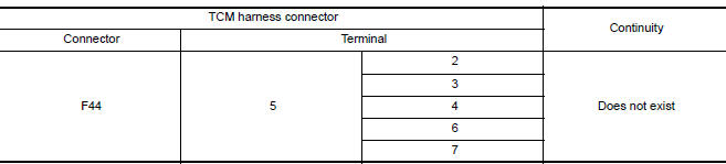
- 6.CHECK P POSITION SW CIRCUIT (CHECK 1)
- Turn ignition switch OFF.
- Disconnect the TCM connector.
- Check the continuity between the TCM harness connector terminals.
Is the check result normal?
YES >> GO TO 7.
NO >> Repair or replace the malfunctioning parts.
7.CHECK P POSITION SW CIRCUIT (CHECK 2)
- Disconnect the transmission range switch connector.
- Turn ignition switch ON.
- Check the voltage between the TCM harness connector and ground.

Is the check result normal?
YES >> GO TO 14.
NO >> Repair or replace the malfunctioning parts.
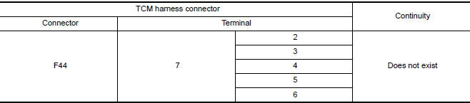
8.CHECK R POSITION SW CIRCUIT (CHECK 1)
- Turn ignition switch OFF.
- Disconnect the TCM connector.
- Check the continuity between the TCM harness connector terminals.
Is the check result normal?
YES >> GO TO 9.
NO >> Repair or replace the malfunctioning parts.
9.CHECK R POSITION SW CIRCUIT (CHECK 2)
- Disconnect the transmission range switch connector.
- Turn ignition switch ON.
- Check the voltage between the TCM harness connector and ground.
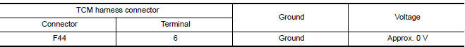
Is the check result normal?
YES >> GO TO 14.
NO >> Repair or replace the malfunctioning parts.
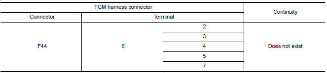
10.CHECK 2 POSITION SW CIRCUIT (CHECK 1)
- Turn ignition switch OFF.
- Disconnect the TCM connector.
- Check the continuity between the TCM harness connector terminals.
Is the check result normal?
YES >> GO TO 11.
NO >> Repair or replace the malfunctioning parts.
11.CHECK 2 POSITION SW CIRCUIT (CHECK 2)
- Disconnect the transmission range switch connector.
- Turn ignition switch ON.
- Check the voltage between the TCM harness connector and ground.

Is the check result normal?
YES >> GO TO 14.
NO >> Repair or replace the malfunctioning parts.
12.CHECK 1 POSITION SW CIRCUIT (CHECK 1)
- Turn ignition switch OFF.
- Disconnect the TCM connector.
- Check the continuity between the TCM harness connector terminals.
Is the check result normal?
YES >> GO TO 13.
NO >> Repair or replace the malfunctioning parts.
13.CHECK 1 POSITION SW CIRCUIT (CHECK 2)
- Disconnect the transmission range switch connector.
- Turn ignition switch ON.
- Check the voltage between the TCM harness connector and ground.

Is the check result normal?
YES >> GO TO 14.
NO >> Repair or replace the malfunctioning parts.
14.CHECK TRANSMISSION RANGE SWITCH
Check the transmission range switch. Refer to TM, "Component Inspection (Transmission Range Switch)".
Is the check result normal?
YES >> Check intermittent incident. Refer to GI, "Intermittent Incident".
NO >> Repair or replace the malfunctioning parts.
Component Inspection (Transmission Range Switch)
1.CHECK TRANSMISSION RANGE SWITCH
Check the continuity between the transmission range switch connector
terminals. 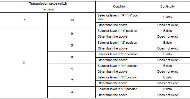
Is the check result normal?
YES >> INSPECTION END
NO >> There is a malfunction of the transmission range switch. Replace the transaxle assembly. Refer to TM, "Removal and Installation".
 P062F EEPROM
Description TCM checks the value read in FLASH ROM at ignition switch ON, and judges if there is writing failure to FLASH ROM or malfunction of FLASH ROM. DTC Logic DTC DETECTION LOGIC ...
P0706 Transmission range sensor A
DTC Logic DTC DETECTION LOGIC DTC Trouble diagnosis name DTC detection condition Possible causes P0706 Transmission Range Sensor "A" Circuit Range/Performance The ...
Other materials:
Oil filter
Removal and Installation
REMOVAL
Remove engine under cover.
Drain engine oil.
Remove oil filter using Tool (A).
: Front
Tool number : KV10115801 (J38956)
WARNING:
Be careful not to get burned; engine and engine oil may be
hot.
CAUTION:
When removing, prepare a shop cl ...
P2760 Torque converter
Description
This DTC is detected when the torque converter clutch solenoid valve is
electrically normal but the torque converter
clutch does not engage. This is not due to an electrical malfunction (circuit
open or shorted), but is
instead due to a mechanical malfunction (sticking of the con ...
Categories
- Manuals Home
- Nissan Versa Owners Manual
- Nissan Versa Service Manual
- Video Guides
- Questions & Answers
- External Resources
- Latest Updates
- Most Popular
- Sitemap
- Search the site
- Privacy Policy
- Contact Us

0.0047