Nissan Versa (N17): P0711 Transmission fluid temperature sensor A
DTC Logic
DTC DETECTION LOGIC
| DTC | Trouble diagnosis name | DTC detection condition | Possible causes |
| P0711 | Transmission Fluid Temperature Sensor A Circuit Range/ Performance | Under the following diagnosis conditions, CVT
fluid temperature does not rise to 10C (50F)
after driving for a certain period of time with the
TCM-received fluid temperature sensor value
between −40C (−40F) and 9C (48.2F). - Diagnosis condition - Selector lever: "D" position - Vehicle speed: 10 km/h (7 MPH) or more - Engine speed: 450 rpm or more - Accelerator pedal position: 1.0/8 or more - TCM power supply voltage: More than 11 V |
CVT fluid temperature sensor |
| When the condition of the final judgment is satisfied
after satisfying that of the provisional
judgment: - Provisional judgment: All of the following conditions are satisfied within 2 seconds after the ignition switch is turned ON. - U0073, U0100, P0712 and P0713 are not detected. - CAN communication is normal. - TCM power supply voltage: More than 11 V - The difference between CVT fluid temperature and engine coolant temperature is 37C (98.6F) or more, or −27C (−16.6F) or less. - Final judgment: When all of the following conditions are satisfied and this state is maintained for 300 seconds: - ECM is normal. - Provisional judgment is satisfied. |
CVT fluid temperature sensor |
DTC CONFIRMATION PROCEDURE
CAUTION: Always drive vehicle at a safe speed.
1.PREPARATION BEFORE WORK
If another "DTC CONFIRMATION PROCEDURE" occurs just before, turn ignition switch OFF and wait for at least 10 seconds, then perform the next test.
>> GO TO 2.
2.CHECK CVT FLUID TEMPERATURE SENSOR FUNCTION
With CONSULT
- Cool the engine.
- Turn ignition switch ON. CAUTION: Never start the engine.
- Select "FLUID TEMP" in "Data Monitor" in "TRANSMISSION".
- Select "COOLANT TEMP/S" in "Data Monitor" in "ENGINE".
- Check temperature difference between CVT fluid and engine coolant.
With GST
- Complete engine diagnoses P0111, P0116, and P0196.
- After starting the engine start, run the engine at idle for 5 minutes.
- Check the DTC.
Is the temperature calculated by subtracting engine coolant temperature from CVT fluid temperature more than 37C (98.6F) or is it less than −27C (−16.6F)? (With CONSULT)/Is "P0711" detected? (With GST)
YES >> Go to TM "Diagnosis Procedure".
NO-1 [With CONSULT: "FLUID TEMP" is 10C (50F) or more]>>INSPECTION END
NO-2 [With CONSULT: "FLUID TEMP" is 9C (48.2F) or less]>>GO TO 3.
NO-3 (With GST)>>GO TO 3.
3.CHECK DTC DETECTION
With CONSULT
- Select "SLCT LVR POSI", "VSP SENSOR", "ACCELE POSI SEN 1", "FLUID TEMP" in "Data Monitor" in "TRANSMISSION".
- Record CVT fluid temperature.
- Start the engine and wait for at least 3 minutes.
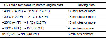
- Drive the vehicle for the total minuets specified in the Driving time column below with the following conditions satisfied.
SLCT LVR POSI : D VSP SENSOR : 10 km/h (7 MPH) or more ACCELE POSI SEN 1 : 1.0/8 or more
5. Perform "Self Diagnostic Results" in "TRANSMISSION".
With GST
1. Cool the engine.
2. Start the engine and wait for at least 3 minutes.
3. Drive the vehicle and maintain the following conditions for 21 minutes or more.
Selector lever : D position Vehicle speed : 10 km/h (7 MPH) or more Accelerator pedal opening : 1.0/8 or more
4. Check the DTC.
Is "P0711" detected?
YES >> Go to TM "Diagnosis Procedure".
NO >> INSPECTION END
Diagnosis Procedure
1.CHECK CVT FLUID TEMPERATURE SENSOR
- Turn ignition switch OFF.
- Disconnect CVT unit connector.
- Check CVT fluid temperature sensor. Refer to TM "Component Inspection (CVT Fluid Temperature Sensor)".
Is the inspection result normal?
YES >> Check intermittent incident. Refer to GI "Intermittent Incident".
NO >> Repair or replace malfunctioning parts.
Component Inspection (CVT Fluid Temperature Sensor)
1.CHECK CVT FLUID TEMPERATURE SENSOR
Check resistance between CVT unit connector terminals. 
Is the inspection result normal?
YES >> INSPECTION END
NO >> There is a malfunction of CVT fluid temperature sensor. Replace transaxle assembly. Refer to TM "Removal and Installation".
 P0706 Transmission range sensor A
P0712 Transmission fluid temperature
sensor A
DTC Logic DTC DETECTION LOGIC DTC Trouble diagnosis name DTC detection condition Possible causes P0712 Transmission Fluid Temperature Sensor A Circuit Low The CVT ...
Other materials:
Precautions when starting and driving
WARNING
Do not leave children or adults who
would normally require the assistance
of others alone in your vehicle. Pets
should also not be left alone. They
could accidentally injure themselves or
others through inadvertent operation of
the vehicle. Also, on hot, sunny days,
tempera ...
P0963 Pressure control solenoid A
DTC Logic
DTC DETECTION LOGIC
DTC
Trouble diagnosis name
DTC detection condition
Possible causes
P0963
Pressure Control Solenoid "A"
Control Circuit High
The following diagnosis conditions
are met, and the current
monitor reading of the TCM line
pressure ...
Categories
- Manuals Home
- Nissan Versa Owners Manual
- Nissan Versa Service Manual
- Video Guides
- Questions & Answers
- External Resources
- Latest Updates
- Most Popular
- Sitemap
- Search the site
- Privacy Policy
- Contact Us

0.0052