
Nissan Versa (N17): P0715 Input speed sensor A
DTC Logic
DTC DETECTION LOGIC
| DTC | Trouble diagnosis name | DTC detection condition | Possible causes |
| P0715 | Input/Turbine Speed Sensor A Circuit | The primary speed sensor value is less than
150 rpm continuously for 5 seconds or more
under the following diagnosis conditions: - Diagnosis conditions - Secondary pulley speed: 1,000 rpm or more - TCM power supply voltage: More than 11 V |
- Harness or connector
(Primary speed sensor circuit is open
or shorted) - Primary speed sensor |
| The primary speed sensor value is 240 rpm or
less continuously for 500 msec or more under
the following diagnosis conditions: - Diagnosis conditions - 10-msec-ago primary pulley speed: 1,000 rpm or more - TCM power supply voltage: More than 11 V |
DTC CONFIRMATION PROCEDURE
CAUTION: Be careful of the driving speed.
1.PREPARATION BEFORE WORK
If another "DTC CONFIRMATION PROCEDURE" occurs just before, turn ignition switch OFF and wait for at least 10 seconds, then perform the next test.
>> GO TO 2.
2.CHECK DTC DETECTION
- Start the engine.
- Drive the vehicle.
- Maintain the following conditions for 10 seconds or more.
- Stop the vehicle.
- Check the first trip DTC.
Selector lever : "L" POSITION Vehicle speed : 40 km/h (25 MPH) or more
Is "P0715" detected?
YES >> Go to TM "Diagnosis Procedure".
NO >> INSPECTION END
Diagnosis Procedure
1.CHECK PRIMARY SPEED SENSOR POWER CIRCUIT
- Turn ignition switch OFF.
- Disconnect primary speed sensor connector.
- Turn ignition switch ON.
- Check voltage between primary speed sensor harness connector terminal
and ground.
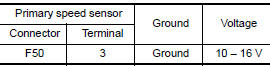
Is the inspection result normal?
YES >> GO TO 2.
NO >> GO TO 6.
2.CHECK PRIMARY SPEED SENSOR GROUND CIRCUIT
Check continuity between primary speed sensor harness connector terminal and
ground. 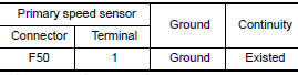
Is the inspection result normal?
YES >> GO TO 3.
NO >> Repair or replace malfunctioning parts.
3.CHECK CIRCUIT BETWEEN PRIMARY SPEED SENSOR AND TCM (PART 1)
- Turn ignition switch OFF.
- Disconnect TCM connector.
- Check continuity between primary speed sensor harness connector terminal
and TCM harness connector
terminal.

Is the inspection result normal?
YES >> GO TO 4.
NO >> Repair or replace malfunctioning parts.
4.CHECK CIRCUIT BETWEEN PRIMARY SPEED SENSOR AND TCM (PART 2)
Check continuity between primary speed sensor harness connector terminal and
ground. 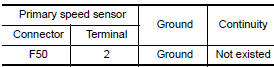
Is the inspection result normal?
YES >> GO TO 5.
NO >> Repair or replace malfunctioning parts.
5.CHECK TCM INPUT SIGNALS
- Connect all of disconnected connectors.
- Lift the vehicle.
- Start the engine.
- Check frequency of primary speed sensor.
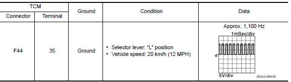
Is the inspection result normal?
YES >> Check intermittent incident. Refer to GI "Intermittent Incident".
NO >> Replace primary speed sensor. TM "Removal and Installation".
6.CHECK CIRCUIT BETWEEN IPDM E/R AND PRIMARY SPEED SENSOR (PART 1)
- Disconnect IPDM E/R connector.
- Check continuity between IPDM E/R harness connector terminal and primary
speed sensor harness connector terminal.

6.CHECK CIRCUIT BETWEEN IPDM E/R AND PRIMARY SPEED SENSOR (PART 1)
- Disconnect IPDM E/R connector.
- Check continuity between IPDM E/R harness connector terminal and primary
speed sensor harness connector terminal.
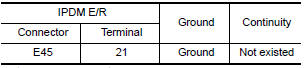
Is the check result normal?
YES >> GO TO 8.
NO >> Repair or replace malfunctioning parts.
8.DETECT MALFUNCTIONING ITEMS
Check the following items:
- Harness open circuit or short circuit between ignition switch and IPDM E/R. Refer to PG "Wiring Diagram - Ignition Power Supply -".
- 10A fuse (No.49, IPDM E/R). Refer to PG "IPDM E/R Terminal Arrangement".
- IPDM E/R
Is the check result normal?
YES >> Check intermittent incident. Refer to GI "Intermittent Incident".
NO >> Repair or replace malfunctioning parts.
 P0713 Transmission fluid temperature
sensor A
P0713 Transmission fluid temperature
sensor A
Other materials:
P0506 ISC system
Description
The ECM controls the engine idle speed to a specified level through the fine
adjustment of the air, which is let
into the intake manifold, by operating the electric throttle control actuator.
The operating of the throttle valve is
varied to allow for optimum control of the engine ...
Malfunction indicator lamp
Component Function Check
1.CHECK MIL FUNCTION
Turn ignition switch ON.
Make sure that MIL lights up.
Is the inspection result normal?
YES >> INSPECTION END
NO >> Go to EC, "Diagnosis Procedure".
Diagnosis Procedure
1.CHECK DTC
Check that DTC UXXXX is not display ...
Categories
- Manuals Home
- Nissan Versa Owners Manual
- Nissan Versa Service Manual
- Video Guides
- Questions & Answers
- External Resources
- Latest Updates
- Most Popular
- Sitemap
- Search the site
- Privacy Policy
- Contact Us

0.0059