Nissan Versa (N17): P0966 Pressure control solenoid B
DTC Logic
DTC DETECTION LOGIC
| DTC | Trouble diagnosis name | DTC detection condition | Possible causes |
| P0966 | Pressure control solenoid B control circuit low | The primary pressure solenoid valve current is
200 mA or less continuously for 480 msec or
more under the following diagnosis conditions: - Diagnosis conditions - Solenoid valve output current: 750 mA or more - GND short circuit diagnosis occurs in the solenoid valve drive circuit. - TCM power supply voltage: More than 11 V |
- Harness or connector
(Primary pressure solenoid valve circuit
shorted to ground) - Primary pressure solenoid valve |
DTC CONFIRMATION PROCEDURE
1.PREPARATION BEFORE WORK
If another "DTC CONFIRMATION PROCEDURE" occurs just before, turn ignition switch OFF and wait for at least 10 seconds, then perform the next test.
>> GO TO 2.
2.CHECK DTC DETECTION
- Start the engine and wait for 5 seconds or more.
- Check the first trip DTC.
Is "P0966" detected?
YES >> Go to TM "Diagnosis Procedure".
NO >> INSPECTION END
Diagnosis Procedure
1.CHECK CIRCUIT BETWEEN TCM AND CVT UNIT
- Turn ignition switch OFF.
- Disconnect TCM connector and CVT unit connector.
- Check continuity between TCM harness connector terminal and ground.
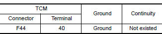
Is the inspection result normal?
YES >> GO TO 2.
NO >> Repair or replace malfunctioning parts.
2.CHECK PRIMARY PRESSURE SOLENOID VALVE
Check primary pressure solenoid valve. Refer to TM "Component Inspection (Primary Pressure Solenoid Valve)".
Is the inspection result normal?
YES >> Check intermittent incident. Refer to GI "Intermittent Incident".
NO >> Repair or replace malfunctioning parts.
Component Inspection (Primary Pressure Solenoid Valve)
1.CHECK PRIMARY PRESSURE SOLENOID VALVE
Check resistance between CVT unit connector terminal and ground. 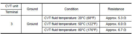
Is the inspection result normal?
YES >> INSPECTION END
NO >> There is a malfunction of primary pressure solenoid valve. Replace transaxle assembly. Refer to TM "Removal and Installation".
 P0965 Pressure control solenoid B
DTC Logic DTC DETECTION LOGIC DTC Trouble diagnosis name DTC detection condition Possible causes P0965 Pressure control solenoid B control circuit range performance ...

Other materials:
S connector circuit
Description
The starter motor magnetic switch is supplied with power when the ignition
switch is turned to the START position
while the selector lever is in the P (Park) or N (Neutral) position.
Diagnosis Procedure
Regarding Wiring Diagram information, refer to STR, "Wiring Diagram - Wit ...
Transmitter wake up operation
Description
This procedure must be performed after replacement of a transmitter or the
BCM, or rotation of the wheels.
Work Procedure
NOTE:
This procedure must be done after replacement of a TPMS transmitter or BCM. New
replacement transmitters
are provided "asleep" and must first ...
Categories
- Manuals Home
- Nissan Versa Owners Manual
- Nissan Versa Service Manual
- Video Guides
- Questions & Answers
- External Resources
- Latest Updates
- Most Popular
- Sitemap
- Search the site
- Privacy Policy
- Contact Us

0.0056