Nissan Versa (N17): P2135 TP sensor
DTC Logic
DTC DETECTION LOGIC
NOTE: If DTC P2135 is displayed with DTC P0643, first perform the trouble diagnosis for DTC P0643. Refer to EC, "DTC Logic".
| DTC No. | Trouble diagnosis name | DTC detecting condition | Possible cause |
| P2135 | Throttle position sensor circuit range/performance | Rationally incorrect voltage is sent to ECM compared with the signals from TP sensor 1 and TP sensor 2. |
|
DTC CONFIRMATION PROCEDURE
1.PRECONDITIONING
If DTC Confirmation Procedure has been previously conducted, always perform the following before conducting the next test.
- Turn ignition switch OFF and wait at least 10 seconds.
- Turn ignition switch ON.
- Turn ignition switch OFF and wait at least 10 seconds.
TESTING CONDITION: Before performing the following procedure, confirm that battery voltage is more than 10 V at idle.
>> GO TO 2.
2.PERFORM DTC CONFIRMATION PROCEDURE
- Start engine and let it idle for 1 second.
- Check DTC.
Is DTC detected?
YES >> Go to EC, "Diagnosis Procedure".
NO >> INSPECTION END
Diagnosis Procedure
1.CHECK GROUND CONNECTION
- Turn ignition switch OFF.
- Check ground connection E15. Refer to Ground Inspection in GI, "Circuit Inspection".
Is the inspection result normal?
YES >> GO TO 2.
NO >> Repair or replace ground connection.
2.CHECK THROTTLE POSITION SENSOR POWER SUPPLY CIRCUIT
- Disconnect electric throttle control actuator harness connector.
- Turn ignition switch ON.
- Check the voltage between electric throttle control actuator harness
connector and ground.
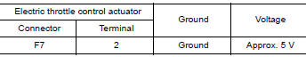
Is the inspection result normal?
YES >> GO TO 3.
NO >> Repair open circuit or short to ground or short to power in harness or connectors.
3.CHECK THROTTLE POSITION SENSOR GROUND CIRCUIT FOR OPEN AND SHORT
- Turn ignition switch OFF.
- Disconnect ECM harness connector.
- Check the continuity between electric throttle control actuator harness
connector and ground.
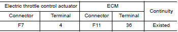
- Also check harness for short to ground and short to power.
Is the inspection result normal?
YES >> GO TO 4.
NO >> Repair open circuit or short to ground or short to power in harness or connectors.
4.CHECK THROTTLE POSITION SENSOR INPUT SIGNAL CIRCUIT FOR OPEN AND SHORT
- Check the continuity between electric throttle control actuator harness
connector and ground.
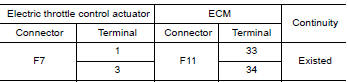
- Also check harness for short to ground and short to power.
Is the inspection result normal?
YES >> GO TO 5.
NO >> Repair open circuit or short to ground or short to power in harness or connectors.
5.CHECK THROTTLE POSITION SENSOR
Refer to EC, "Component Inspection".
Is the inspection result normal?
YES >> GO TO 7.
NO >> GO TO 6.
6.REPLACE ELECTRIC THROTTLE CONTROL ACTUATOR
Replace electric throttle control actuator. Refer to EM, "Removal and Installation".
>> INSPECTION END
7.CHECK INTERMITTENT INCIDENT
Refer to GI, "Intermittent Incident".
>> INSPECTION END
Component Inspection
1.CHECK THROTTLE POSITION SENSOR
- Turn ignition switch OFF.
- Reconnect all harness connectors disconnected.
- Perform EC, "Work Procedure".
- Turn ignition switch ON.
- Set selector lever to D (A/T or CVT) or 1st (M/T) position.
- Check the voltage between ECM harness connector and ground.
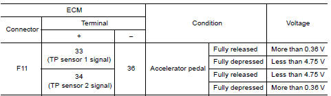
Is the inspection result normal?
YES >> INSPECTION END
NO >> GO TO 2.
2.REPLACE ELECTRIC THROTTLE CONTROL ACTUATOR
Replace electric throttle control actuator. Refer to EM, "Removal and Installation".
>> INSPECTION END
 P2127, P2128 APP sensor
Other materials:
P072E Stuck in 3GR
DTC Logic
DTC DETECTION LOGIC
DTC
Trouble diagnosis name
DTC detection condition
Possible causes
P072E
Stuck in Gear 3
The following diagnosis conditions
are met and the detection
conditions continue for 0.5 seconds
or more.- Diagnosis condition
- Shifti ...
OD OFF indicator lamp
Component Function Check
1.CHECK OD OFF INDICATOR LAMP FUNCTION
Check OD OFF indicator lamp turns ON for approx. 2 seconds when ignition
switch turns ON.
Is the inspection results normal?
YES >> INSPECTION END
NO >> Go to TM "Diagnosis Procedure".
Diagnosis Procedure
...
Categories
- Manuals Home
- Nissan Versa Owners Manual
- Nissan Versa Service Manual
- Video Guides
- Questions & Answers
- External Resources
- Latest Updates
- Most Popular
- Sitemap
- Search the site
- Privacy Policy
- Contact Us

0.0058