Nissan Versa (N17): Power supply and ground circuit
BCM (Body control system) (with intelligent key system)
BCM (BODY CONTROL SYSTEM) (WITH INTELLIGENT KEY SYSTEM) : Diagnosis Procedure
1.CHECK FUSES AND FUSIBLE LINK
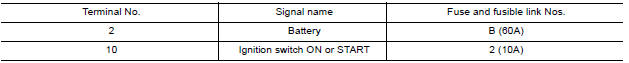
Check that the following fuses and fusible link are not blown.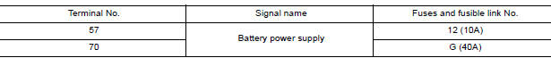
Is the fuse blown?
YES >> Replace the blown fuse or fusible link after repairing the affected circuit.
NO >> GO TO 2.
2.CHECK POWER SUPPLY CIRCUIT
1. Disconnect BCM connector M99.
2. Check voltage between BCM connector M99 and ground.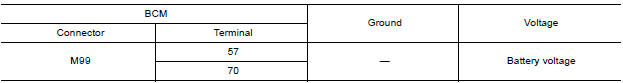
Is the inspection result normal?
YES >> GO TO 3.
NO >> Repair harness or connector.
3.CHECK GROUND CIRCUIT
Check continuity between BCM connector M99 and ground.
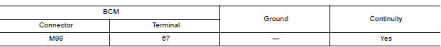
Is the inspection result normal?
YES >> Inspection End.
NO >> Repair harness or connector.
BCM (Body control system) (without intelligent key system)
BCM (BODY CONTROL SYSTEM) (WITHOUT INTELLIGENT KEY SYSTEM) : Diagnosis Procedure
Regarding Wiring Diagram information, refer to BCS "Wiring Diagram".
1.CHECK FUSES AND FUSIBLE LINK
Check that the following fuses and fusible link are not blown.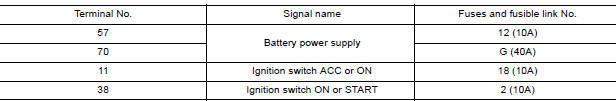
Is the fuse blown?
YES >> Replace the blown fuse or fusible link after repairing the affected circuit.
NO >> GO TO 2.
2.CHECK POWER SUPPLY CIRCUIT
1. Turn ignition switch OFF.
2. Disconnect BCM connectors.
3. Check voltage between BCM connector and ground.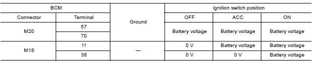
Is the inspection result normal?
YES >> GO TO 3.
NO >> Repair harness or connector.
3.CHECK GROUND CIRCUIT
Check continuity between BCM connector and ground.
Is the inspection result normal?
YES >> Inspection End.
NO >> Repair harness or connector.
IPDM E/R (With intelligent key system)
IPDM E/R (WITH INTELLIGENT KEY SYSTEM) : Diagnosis Procedure
Regarding Wiring Diagram information, refer to PCS "Wiring Diagram".
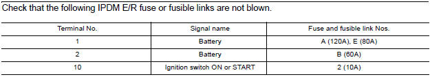
1. CHECK FUSE AND FUSIBLE LINKS
Check that the following IPDM E/R fuse or fusible links are not blown.
Is the fuse blown?
YES >> Replace the blown fuse or fusible link after repairing the affected circuit.
NO >> GO TO 2
2. CHECK BATTERY POWER SUPPLY CIRCUIT
1. Turn ignition switch OFF.
2. Disconnect IPDM E/R.
3. Check voltage between IPDM E/R connectors and ground.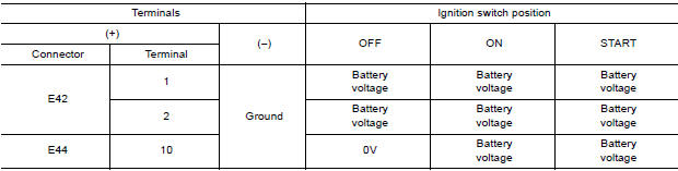
Is the measurement value normal?
YES >> GO TO 3
NO >> Repair or replace harness.
3. CHECK GROUND CIRCUIT
1. Turn ignition switch OFF.
2. Check continuity between IPDM E/R connectors and ground.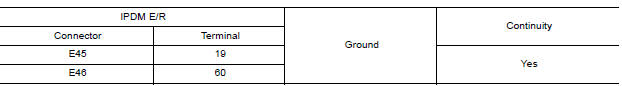
Does continuity exist?
YES >> Inspection End.
NO >> Repair or replace harness.
IPDM E/R (Without intelligent key system)
IPDM E/R (WITHOUT INTELLIGENT KEY SYSTEM) : Diagnosis Procedure
Regarding Wiring Diagram information, refer to PCS "Wiring Diagram".
1. CHECK FUSE AND FUSIBLE LINKS
Is the fuse blown?
YES >> Replace the blown fuse or fusible link after repairing the affected circuit.
NO >> GO TO 2
2. CHECK BATTERY POWER SUPPLY CIRCUIT
1. Turn ignition switch OFF.
2. Disconnect IPDM E/R.
3. Check voltage between IPDM E/R connectors and ground.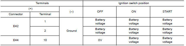
Is the measurement value normal?
YES >> GO TO 3
NO >> Repair or replace harness.
3. CHECK GROUND CIRCUIT
1. Turn ignition switch OFF.
2. Check continuity between IPDM E/R connectors and ground.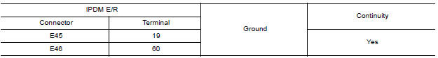
Does continuity exist?
YES >> Inspection End.
NO >> Repair or replace harness
 Diagnosis and repair workflow
Work Flow OVERALL SEQUENCE DETAILED FLOW 1.INTERVIEW FOR MALFUNCTION Find out what the customer's concerns are. >> GO TO 2. 2.SYMPTOM CHECK Verify the symptom from the customer's inf ...
Headlamp (HI) circuit
Description The IPDM E/R (intelligent power distribution module engine room) controls the headlamp high relay based on inputs from the BCM via the CAN communication lines. When the headlamp high ...
Other materials:
Exhaust valve timing control
Exhaust valve timing control : system diagram
Exhaust valve timing control : system description
INPUT/OUTPUT SIGNAL CHART
Sensor
Input signal to ECM
ECM function
Actuator
Crankshaft position sensor (POS)
Engine speed*1
Piston position
Exhaust valve timing c ...
P0712 Transmission fluid temperature
sensor A
DTC Logic
DTC DETECTION LOGIC
DTC
Trouble diagnosis name
DTC detection condition
Possible causes
P0712
Transmission Fluid Temperature
Sensor "A" Circuit Low
Under the following diagnosis
conditions, the A/T fluid temperature
identified by TCM is
180C (3 ...
Categories
- Manuals Home
- Nissan Versa Owners Manual
- Nissan Versa Service Manual
- Video Guides
- Questions & Answers
- External Resources
- Latest Updates
- Most Popular
- Sitemap
- Search the site
- Privacy Policy
- Contact Us

0.0153