Nissan Versa (N17): Push-button ignition switch
Component Function Check
1.CHECK FUNCTION
1. Select "PUSH SW" in "Data Monitor" of BCM with CONSULT.
2. Check the push-button ignition switch signal under the following
conditions.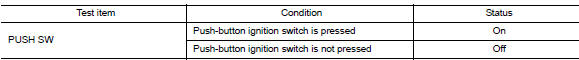
Is the indication normal?
YES >> Inspection End.
NO >> Go to PCS "Diagnosis Procedure".
Diagnosis Procedure
Regarding Wiring Diagram information, refer to PCS "Wiring Diagram".
1. CHECK PUSH-BUTTON IGNITION SWITCH OUTPUT SIGNAL (PUSH-BUTTON IGNITION SWITCH)
1. Turn ignition switch OFF.
2. Disconnect push-button ignition switch connector and IPDM E/R connector E47.
3. Check voltage between push-button ignition switch connector M25 terminal 8
and ground.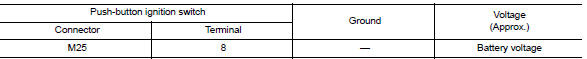
Is the inspection result normal?
YES >> GO TO 3.
NO >> GO TO 2.
2. CHECK PUSH-BUTTON IGNITION SWITCH CIRCUIT (BCM)
1. Disconnect BCM connector M98.
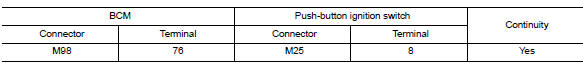
2. Check continuity between BCM connector M98 terminal 76 and push-button
ignition switch connector
M25 terminal 8.
3. Check continuity between BCM connector M98 terminal 76 and ground.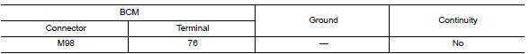
Is the inspection result normal?
YES >> Replace BCM. Refer to BCS "Removal and Installation".
NO >> Repair or replace harness or connectors.
3. CHECK IGNITION SWITCH OUTPUT SIGNAL (IPDM E/R)
Check voltage between IPDM E/R connector E47 terminal 81 and ground.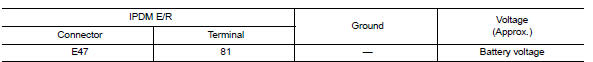
Is the inspection result normal?
YES >> GO TO 5.
NO >> GO TO 4.
4. CHECK PUSH-BUTTON IGNITION SWITCH CIRCUIT (IPDM E/R)
1. Disconnect BCM connector M17.
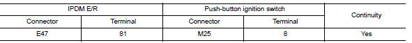
2. Check continuity between IPDM E/R connector E47 terminal 81 and
push-button ignition switch connector
M25 terminal 8.
3. Check continuity between IPDM E/R connector E47 terminal 81 and ground.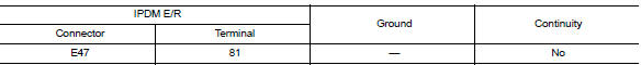
Is the inspection result normal?
YES >> Replace IPDM E/R. Refer to PCS"Removal and Installation".
NO >> Repair or replace harness or connectors.
5.CHECK PUSH-BUTTON IGNITION SWITCH GROUND CIRCUIT
Check continuity between push-button ignition switch connector M25 terminal 4
and ground.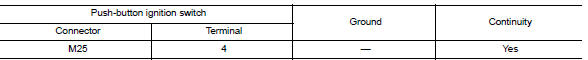
Is the inspection result normal?
YES >> GO TO 6.
NO >> Repair or replace harness or connectors.
6.CHECK PUSH-BUTTON IGNITION SWITCH
Refer to PCS "Component Inspection".
Is the inspection result normal?
YES >> Refer to GI"Intermittent Incident".
NO >> Replace push-button ignition switch.
Component Inspection
1.CHECK PUSH-BUTTON IGNITION SWITCH
1. Turn ignition switch OFF.
2. Disconnect push-button ignition switch connector.
3. Check continuity between push-button ignition switch terminals.
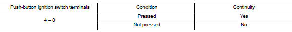
Is the inspection result normal?
YES >> Inspection End.
NO >> Replace push-button ignition switch.
SYMPTOM DIAGNOSIS
 B26F6 BCM
Other materials:
Servicing air conditioner
The air conditioner system in your NISSAN vehicle
is charged with a refrigerant designed with
the environment in mind.
This refrigerant does not harm the earth's
ozone layer.
Special charging equipment and lubricant is required
when servicing your NISSAN air conditioner.
Using improper ...
Fuel pressure check
Work Procedure
FUEL PRESSURE RELEASE
1.FUEL PRESSURE RELEASE
With CONSULT
Turn ignition switch ON.
Perform "FUEL PRESSURE RELEASE" in "WORK SUPPORT" mode with CONSULT.
Start engine.
After engine stalls, crank it two or three times to release all fuel
pressure.
Turn ignition switc ...
Categories
- Manuals Home
- Nissan Versa Owners Manual
- Nissan Versa Service Manual
- Video Guides
- Questions & Answers
- External Resources
- Latest Updates
- Most Popular
- Sitemap
- Search the site
- Privacy Policy
- Contact Us

0.0056