Nissan Versa (N17): Radiator core support lower
RADIATOR CORE SUPPORT LOWER : Removal and Installation
RADIATOR CORE SUPPORT LOWER
Removal
1. Remove under cover. Refer to EXT "Removal and Installation".
2. Remove radiator upper seal clips.
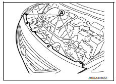
3. Remove front bumper fascia upper side clips (A).
4. Remove fender protector (LH/RH) clips from radiator core support lower. Refer to EXT "Removal and Installation".
5. Remove lower clips of radiator side seal (LH/RH).
6. Remove lower clips of condenser side seal.
7. Use suitable tools (A) to suspend components and to prevent them from falling.
CAUTION: Use care to avoid damage to radiator and condenser.
8. Remove radiator core support lower bolts and radiator core support lower.
Installation
Installation is in the reverse order of removal.
FRONT FENDER
Exploded View
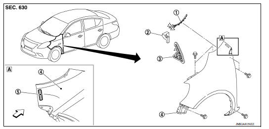
1. Front fender cover 2. Front fender seal 3. Front fender upper insulator
4. Front fender 5. Front fender stiffener  Front
Front
 Pawl
Pawl
 Radiator core support upper
RADIATOR CORE SUPPORT UPPER : Removal and Installation RADIATOR CORE SUPPORT UPPER Removal 1. Remove ground harness bolt (A). 2. Remove horn. Refer to HRN "Removal and Installation" ...
Front fender
FRONT FENDER : Removal and Installation CAUTION: Use a shop cloths to protect the body from being damaged during removal and installation. REMOVAL Remove fender protector. Refer to EXT " ...
Other materials:
Camshaft valve clearance
Inspection and Adjustment
INSPECTION
Perform inspection as follows after removal, replacement or installation of
camshaft or valverelated parts, or if
there are unusual engine conditions regarding valve clearance.
Remove rocker cover.
Measure the valve clearance with the following proced ...
P073E Unable to engage r range
Description
This malfunction is detected when the A/T does not shift into reverse
position as instructed by TCM. This is not
only caused by electrical malfunction (circuits open or shorted) but by
mechanical malfunction such as control
valve sticking, improper solenoid valve operation, etc
D ...
Categories
- Manuals Home
- Nissan Versa Owners Manual
- Nissan Versa Service Manual
- Video Guides
- Questions & Answers
- External Resources
- Latest Updates
- Most Popular
- Sitemap
- Search the site
- Privacy Policy
- Contact Us

0.0053