Nissan Versa (N17): Rear door speaker
Diagnosis Procedure
Regarding Wiring Diagram information, refer to AV "Wiring Diagram".
1.CONNECTOR CHECK
Check the audio unit and speaker connectors for the following:
- Proper connection
- Damage
- Disconnected or loose terminals
Is the inspection result normal?
YES >> GO TO 2
NO >> Repair the terminals or connectors.
2.CHECK REAR DOOR SPEAKER SIGNAL CIRCUIT CONTINUITY
1. Disconnect audio unit connector M46 and suspect rear door speaker connector.
2. Check continuity between audio unit connector M46 and suspect rear door
speaker connector.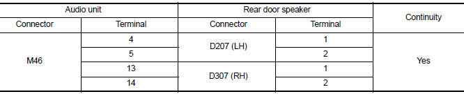
3. Check continuity between audio unit connector M46 and ground.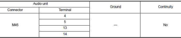
Is the inspection result normal?
YES >> GO TO 3
NO >> Repair or replace harness or connectors.
3.CHECK REAR DOOR SPEAKER SIGNAL
1. Connect audio unit connector M46 and suspect rear door speaker connector.
2. Turn ignition switch to ACC.
3. Push audio unit POWER switch.
4. Check signal between the terminals of audio unit connector M46.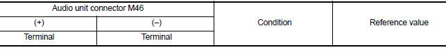
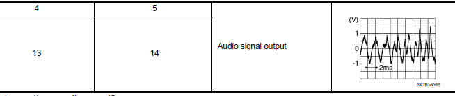
Is the inspection result normal?
YES >> Replace rear door speaker. Refer to AV "Removal and Installation".
NO >> Replace audio unit. Refer to AV "Removal and Installation".
 Front door speaker
Diagnosis Procedure Regarding Wiring Diagram information, refer to AV "Wiring Diagram". 1.CONNECTOR CHECK Check the audio unit and speaker connectors for the following: Proper connect ...
Bluetooth voice signal circuit
Diagnosis Procedure Regarding Wiring Diagram information, refer to AV "Wiring Diagram". 1.CHECK BLUETOOTH VOICE SIGNAL CIRCUIT CONTINUITY 1. Turn ignition switch OFF. 2. Disconnect audio ...
Other materials:
Towing a trailer
Flat towing
Do not tow a trailer with your vehicle.
Towing your vehicle with all four wheels on the
ground is sometimes called flat towing. This
method is sometimes used when towing a vehicle
behind a recreational vehicle, such as a motor
home.
CAUTION
Failure to follow these guidelines c ...
P0743 Torque converter
DTC Logic
DTC DETECTION LOGIC
DTC
Trouble diagnosis name
DTC detection condition
Possible causes
P0743
Torque Converter Clutch Circuit
Electrical
The following diagnosis conditions
are met, and the TCM
torque converter clutch solenoid
valve current monito ...
Categories
- Manuals Home
- Nissan Versa Owners Manual
- Nissan Versa Service Manual
- Video Guides
- Questions & Answers
- External Resources
- Latest Updates
- Most Popular
- Sitemap
- Search the site
- Privacy Policy
- Contact Us

0.007